Other articles in this series:
This device is a rebadge of the ETommens eTM-xxxxP series of programmable power supplies, and this power supply specifically looks the closest. This teardown should be fairly applicable to the: Hanmatek HM305P, Rockseed RS305P, Hanmatek HM310P, RockSeed RS310P, Rockseed RS605P, eTommens eTM305P, eTommens eTM3010P, eTommens eTM1003P, eTommens eTM1520P, eTommens eTM605P, and eTommens eTM1502P.
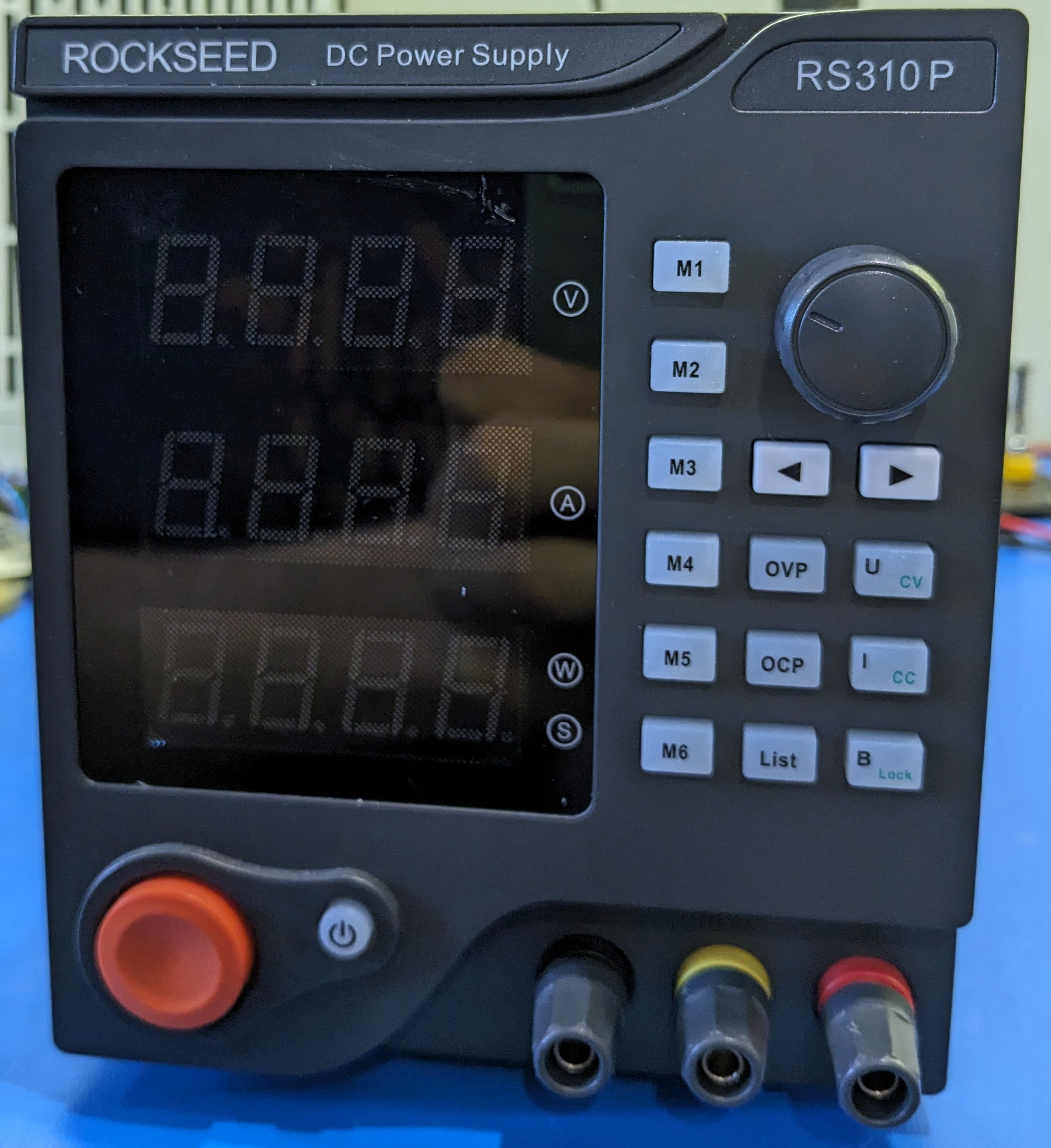
This page contains my rough notes on reverse engineering the ROCKSEED RS310P programmable power supply. I’ve focused on the control electronics.
Prior work
- the sigrok wiki
- this specific device on the sigrok wiki
- a similar device on the EEVBlog forums
- there’s a software package to control it programmatically over serial
Photos
Analysis
Coarse feedback
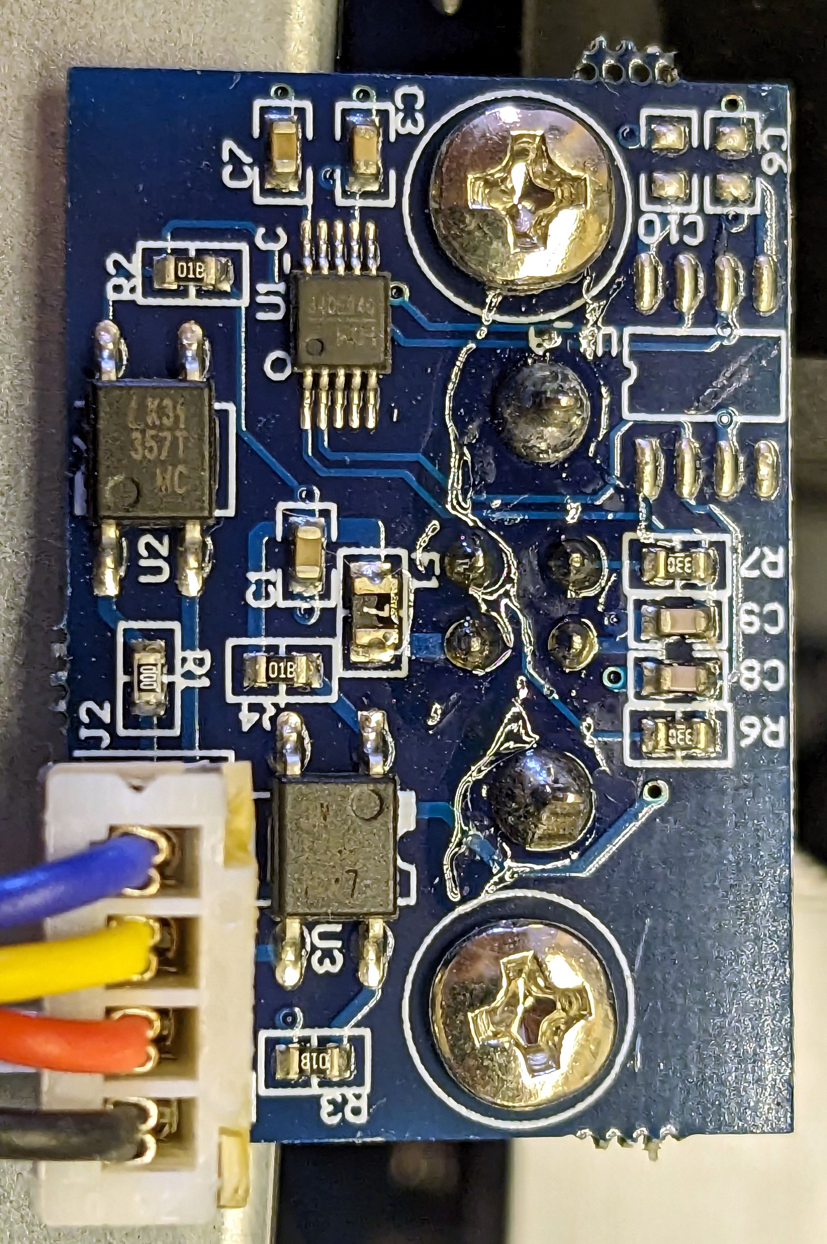
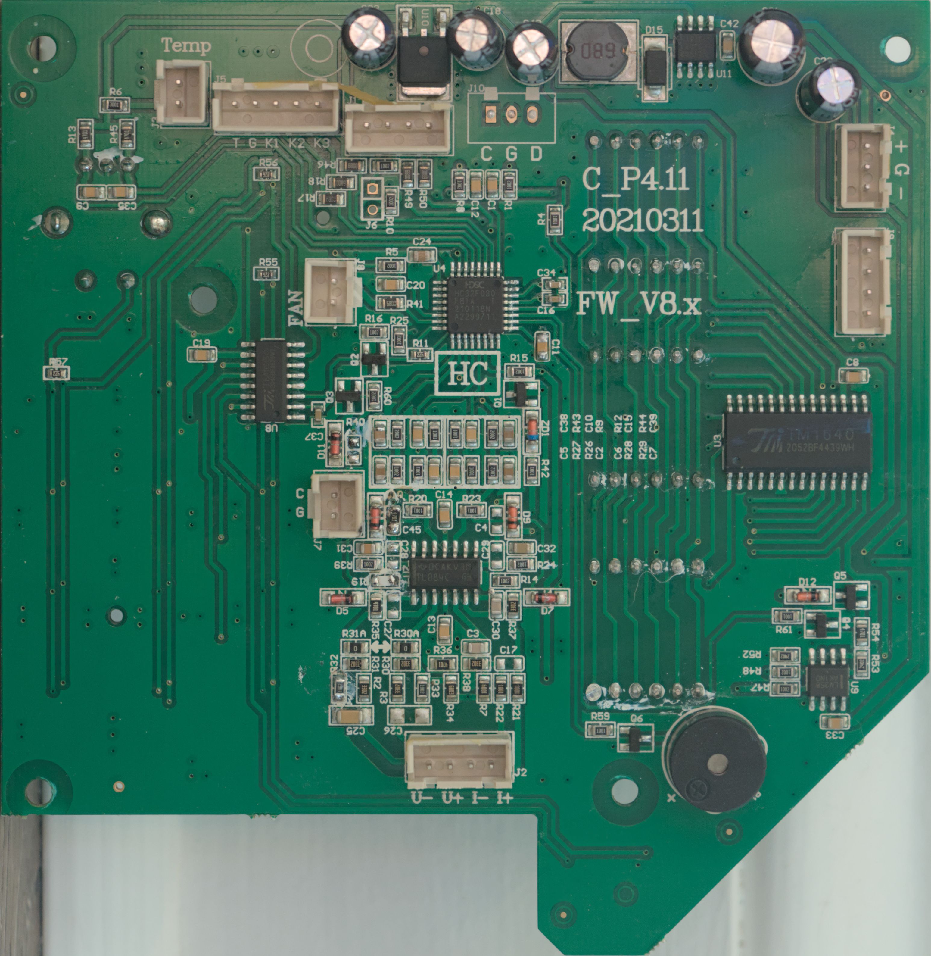
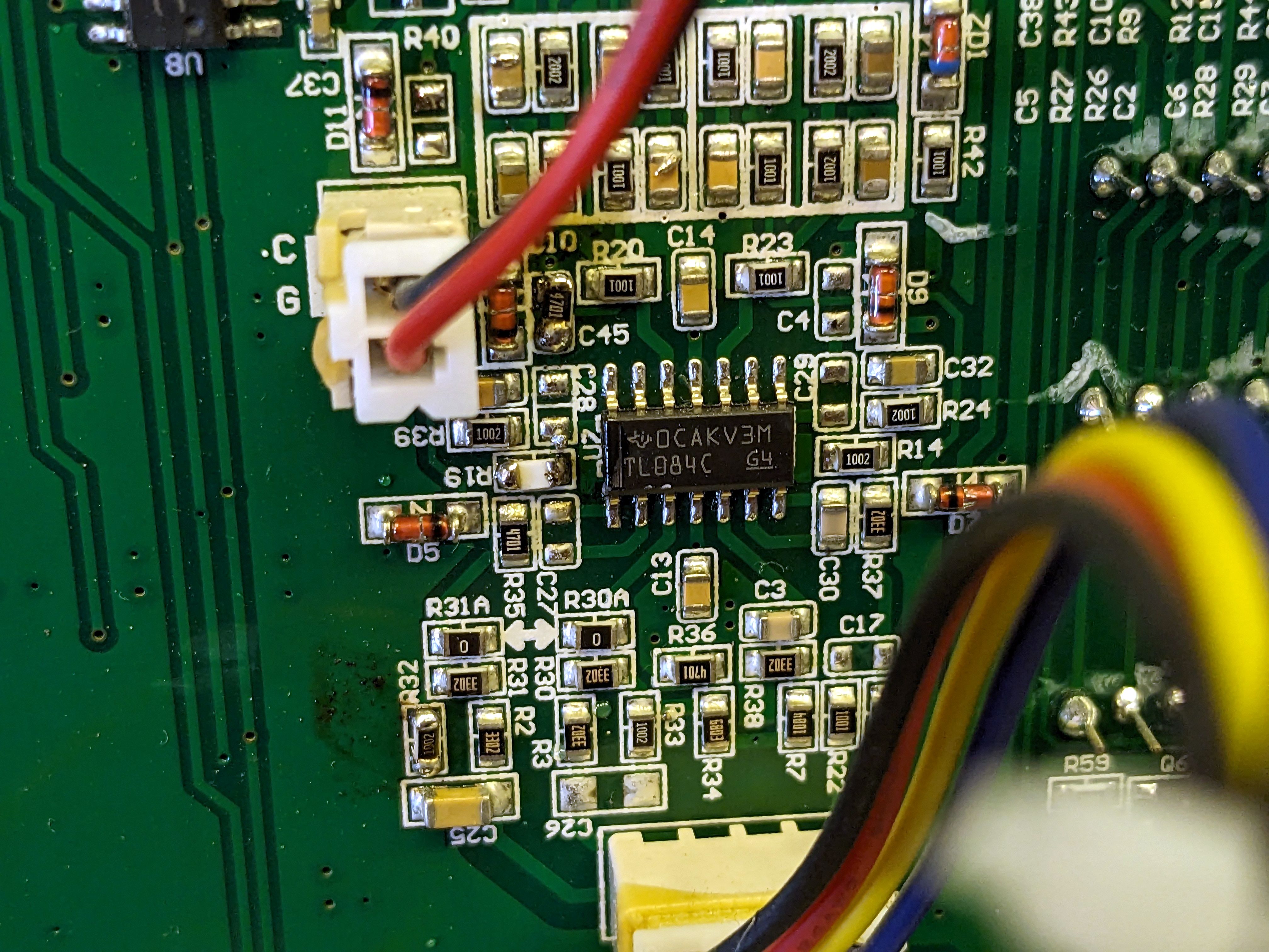
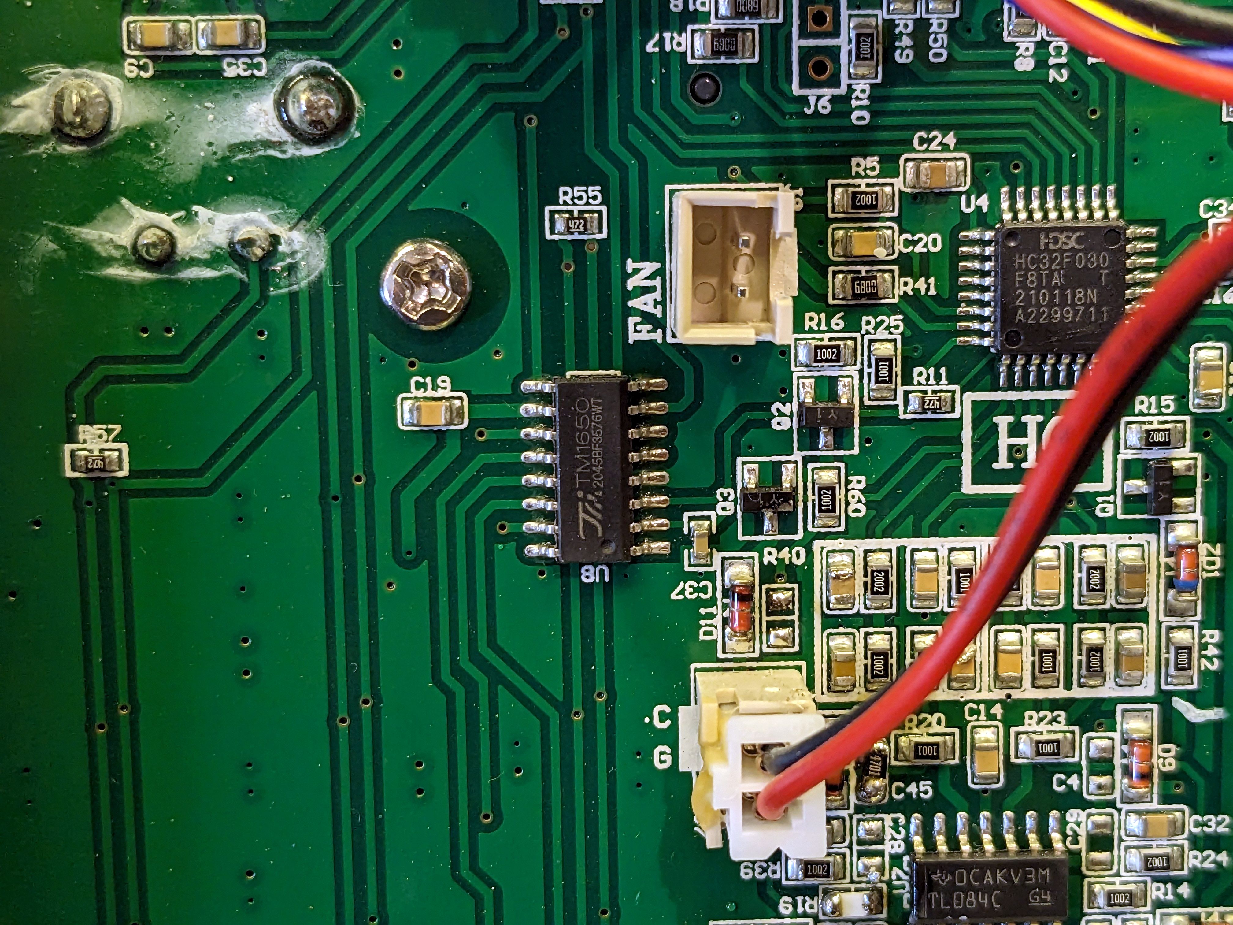
Voltage & current feedback signals are fed into the control board from the power board. They are not measured at the binding posts, but rather at the power board’s output. The control board then uses a TI TL084 quad op-amp to convert these signals to a readable voltage and feeds them into the HC32F030F8TA microcontroller.
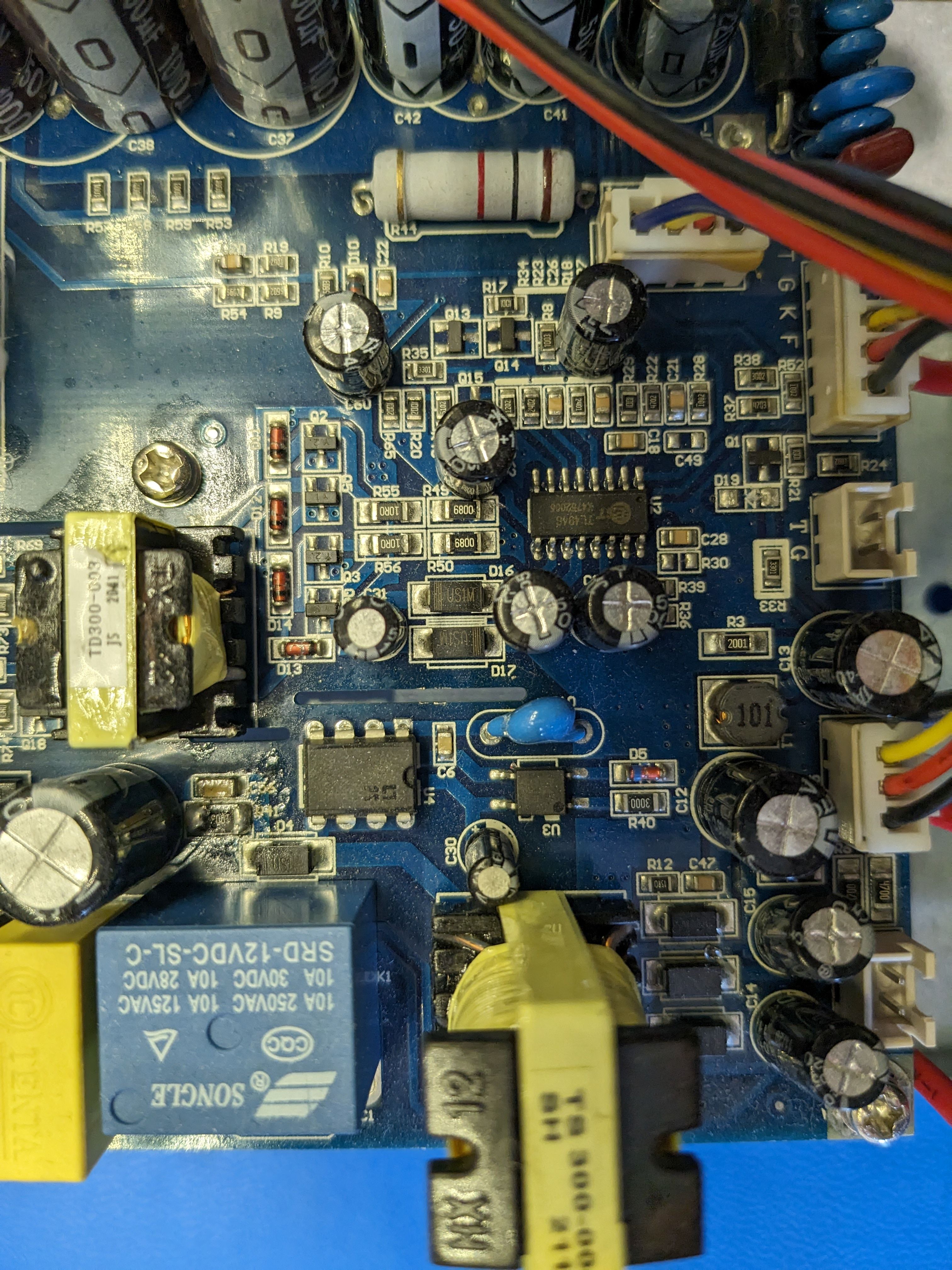
The power board uses a TI TL494 PWM controller to generate the PWM signals for the buck converter. TL494 is connected to the control board by the J5 connector. I haven’t traced the purpose of these signals, but the TL494 has two error amplifiers that these likely feed into.
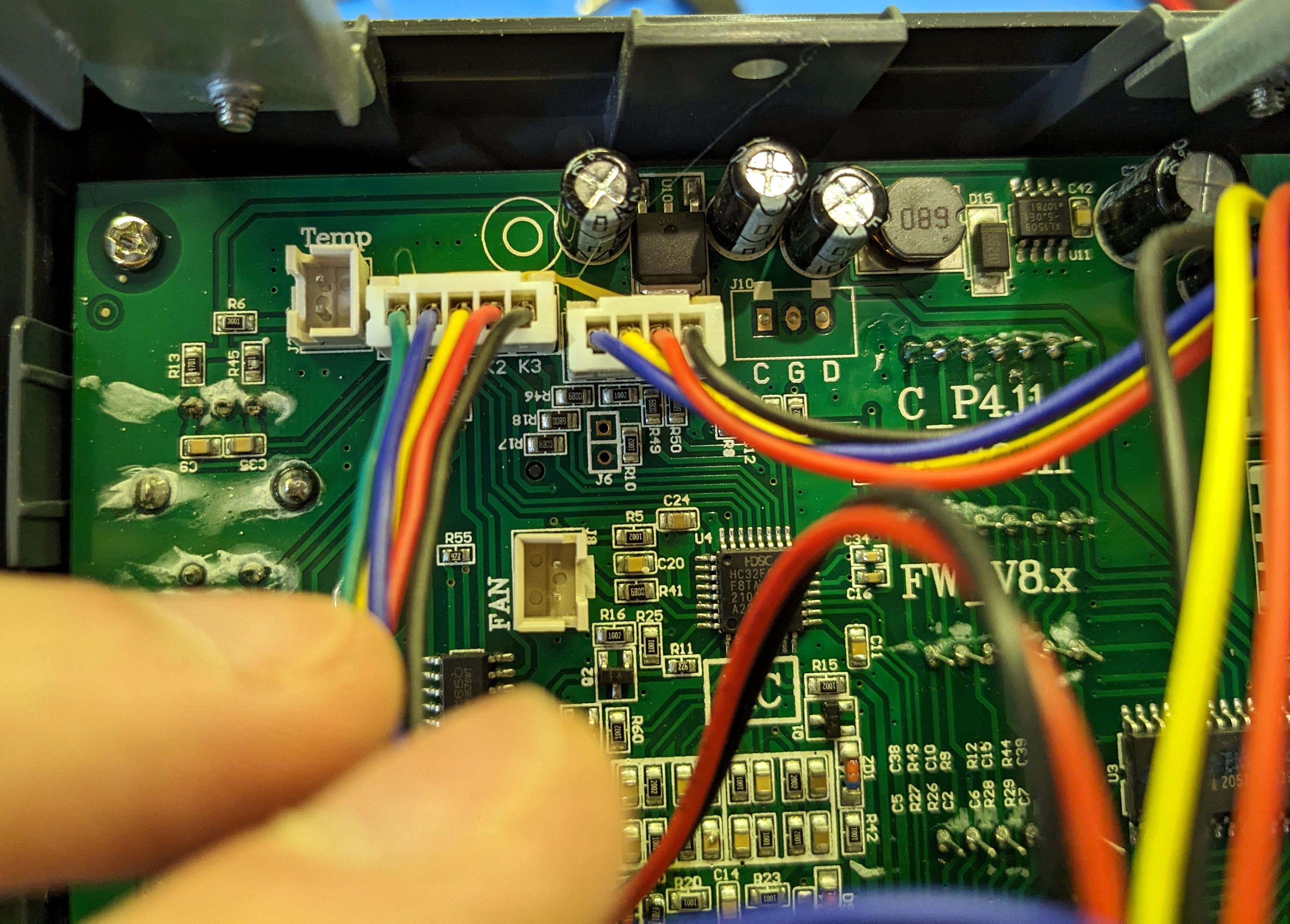
J2 pinout
| # | Color | Purpose |
|---|---|---|
| 1 | Blue | I+ Sense |
| 2 | Yellow | I- Sense |
| 3 | Red | V+ Sense |
| 4 | Black | V- Sense |
Programmable controls
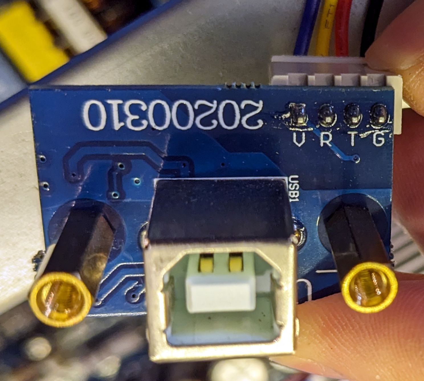
J1 feeds into the UART to USB adapter. This adapter uses a CH340E USB to UART bridge. Cable, in my case, is:
| # | Color | Purpose |
|---|---|---|
| 1 | Blue | 5V |
| 2 | Yellow | RX |
| 3 | Red | TX |
| 4 | Black | GND |
I’m especially interested in this since it should be easy to replace this USB adaptor with a Wifi or Bluetooth UART bridge and then control the power supply over the network.
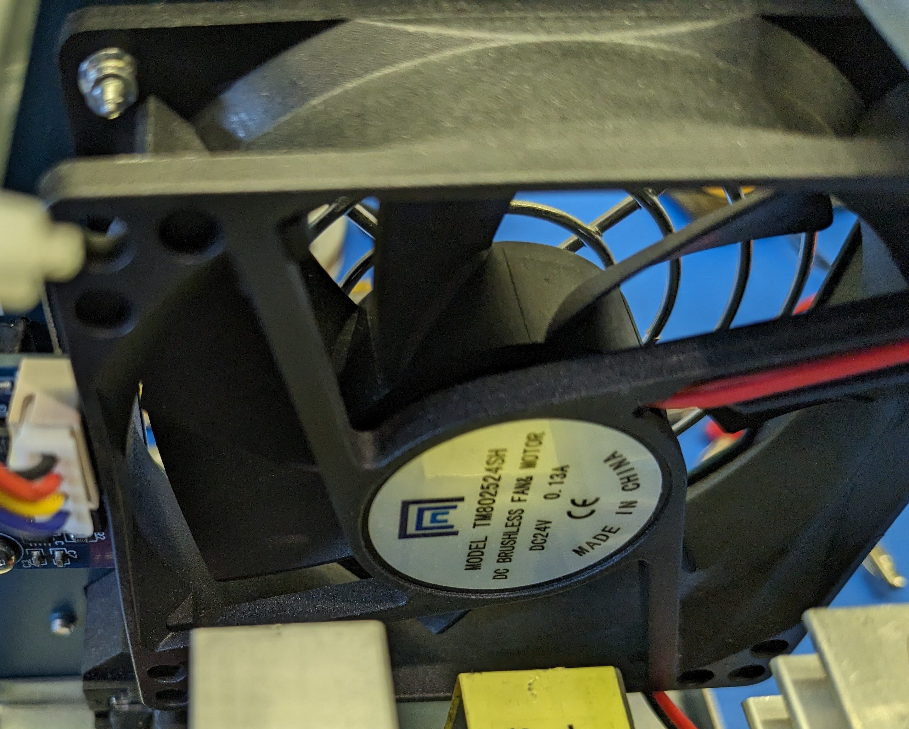
Fan
The fan is a TM802524SH 24V fan by an unknown manufacturer. The temperature sensor is a NTC 4.7kΩ thermistor connected between J5 pins 1 and 2. There is a 3kΩ (R6) pull-up resistor to 5V on pin 1 of J5.
The fan is however not connected to the microcontroller in any way, and is instead controlled by the power board, where an increase in load (regardless of temperature) will increase the fan speed.
The fan output (J8) on the control board is a 5V on/off signal, not PWM, and has nothing plugged in.
This fan is very loud when it gets going, even if the temperature is low. Conveniently, there is a second, unused, thermistor port connected in parallel to the first, and this connector can be used to read out the temperature & control the fan speed based on temperature.
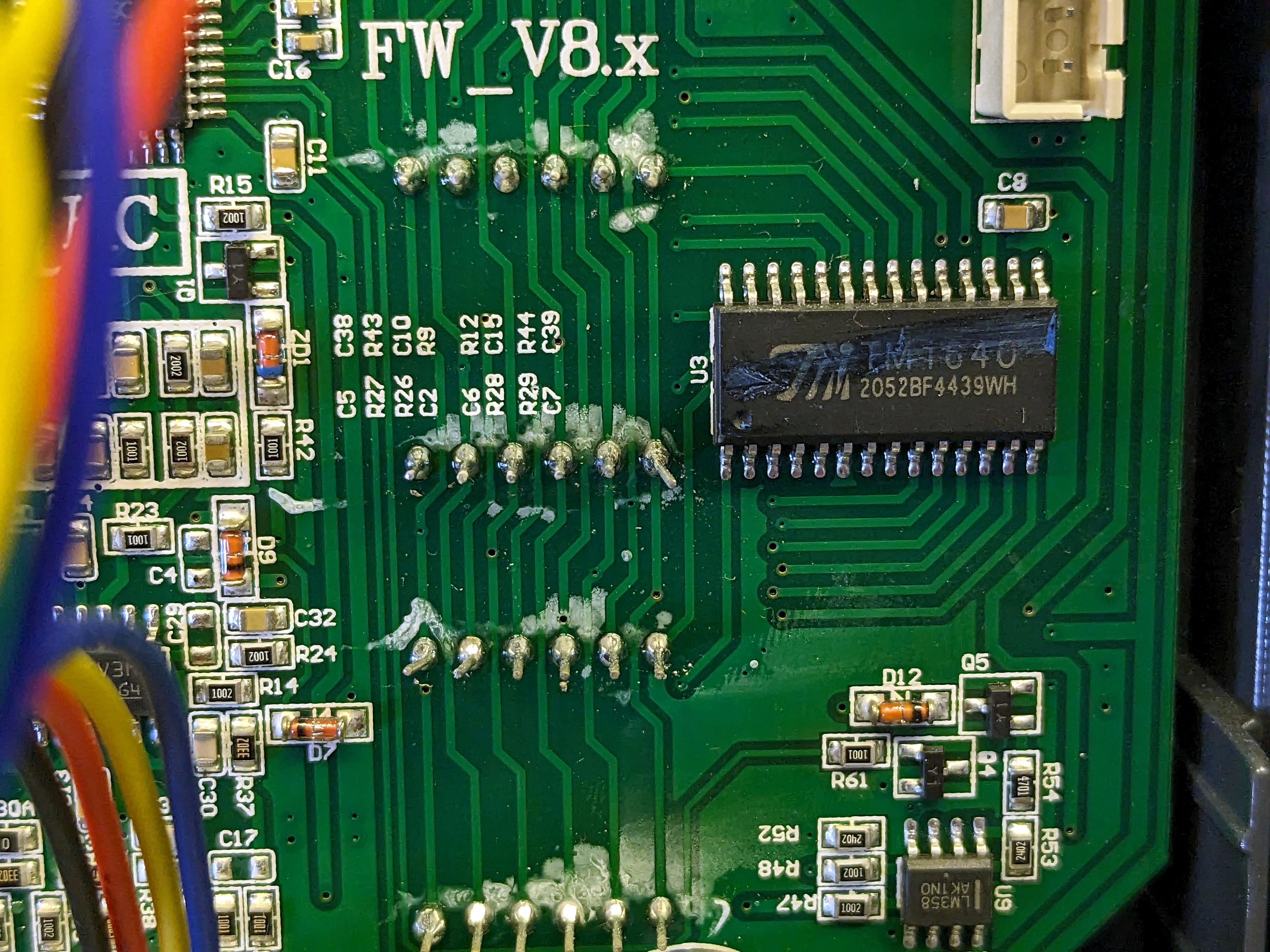
Microcontroller
The microcontroller is an HC32F030F8TA. It’s a 32-bit ARM Cortex-M0 microcontroller with 64KB of flash. I tried to connect to it via SWD, but it seems like the debugger interface is disabled. I suspect power glitching may be able to override this (since this is a register setting, not a fuse), but I don’t know how to do this.
The debug interface is not broken out on the board, so it is necessary to solder wires to the MCU pins.
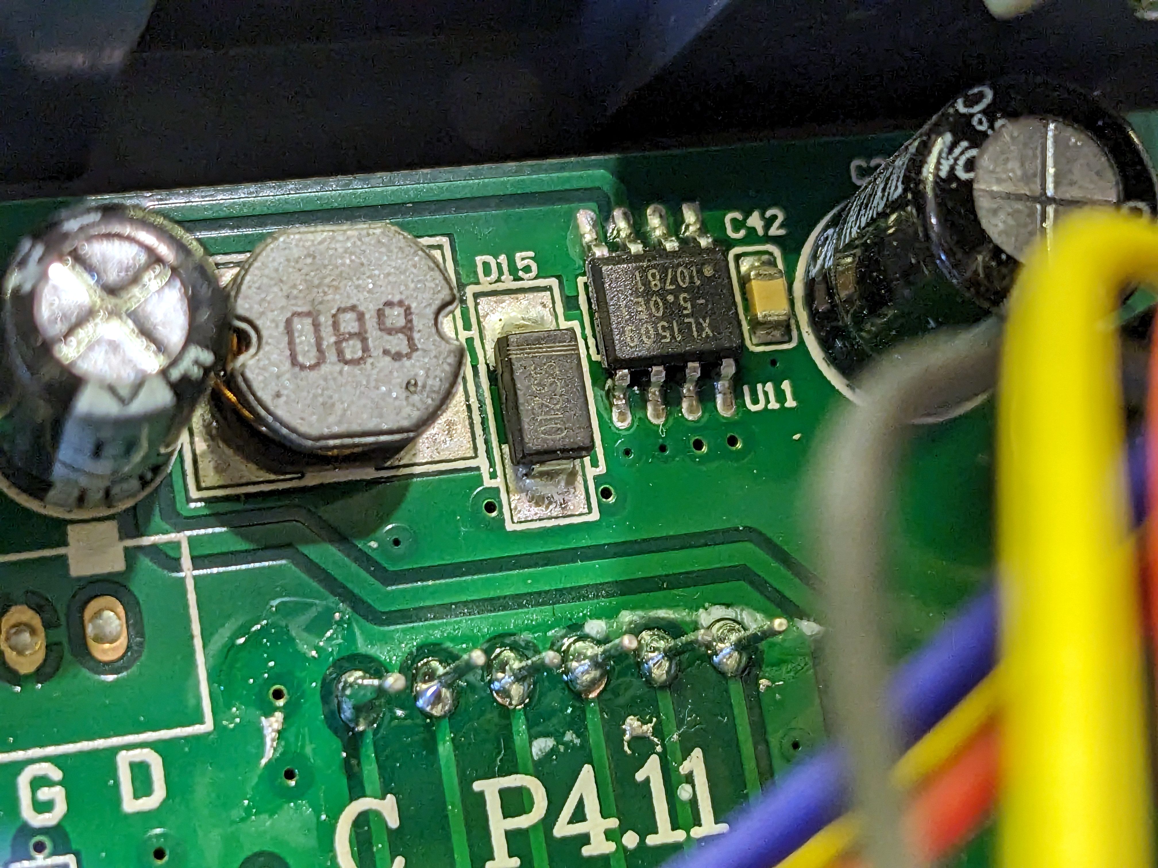
Control power supply
There are two power supplies on the control board, both 5V. U10 is a 5V fixed linear regulator, and U11 is a XL1509-5.0E1 5V buck converter. It’s unclear to me why there are two power supplies for the same voltage, but maybe this is for a analog/digital split?