Other articles in this series:
This device is a rebadge of the ETommens eTM-xxxxP series of programmable power supplies, and this power supply specifically looks the closest. This teardown should be fairly applicable to the: Hanmatek HM305P, Rockseed RS305P, Hanmatek HM310P, RockSeed RS310P, Rockseed RS605P, eTommens eTM305P, eTommens eTM3010P, eTommens eTM1003P, eTommens eTM1520P, eTommens eTM605P, and eTommens eTM1502P.
I’ve previously mentioned that it ought to be fairly easy to connect this power supply’s serial interface to WiFi. I didn’t originally plan to document my process, so pictures are a bit sparse.
I did ths so that I could control the power supply from my computer, using the rs310p_dc_psu software.
Hardware
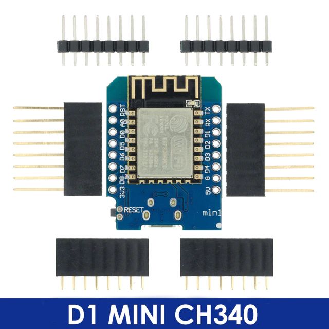
ESP8266 via D1 Mini CH340
You need an ESP8266 board with a voltage regulator to convert the power supply’s 5V to 3.3V. I used a D1 Mini CH340, which worked fine, although I needed to desolder and remove a pull-up resistor on the ESP8266’s RX pin.
ESP-Link only supports the ESP8266, so the ESP32 is not suitable here.
A level shifter is not required because 3.3V on the ESP8266’s TX pin is considered logic high by the 5V MCU on the power supply, and the ESP8266’s RX pin is 5V tolerant.
JST B4B-XH-A
I had a clone JST XH 4-pin connector in my parts bin, so I used that. This is convenient because the power supply can be swapped back to the original USB adapter with no additional work.
Miscellaneous
I also used large clear heatshrink, some hot glue, some jumper wires, and a soldering iron.
Installation
I first installed ESPLink on the ESP8266. I used the 3.2.47.alpha binary. The ESP8266 was connected to my computer via USB, and I ran the following command: esptool.py -b 1000000 -p /dev/ttyUSB1 write_flash --flash_freq 20m --flash_mode dio --flash_size 4MB 0x1000 user1.bin 0x0000 boot_v1.7.bin 0x3fc000 esp_init_data_default.bin 0x3fe000 blank.bin
The ESP8266 was then left connected to my computer while I added it to my WiFi network. I set the baud rate in the “µC Console” tab to 9600 8N1, and made a note of the IP address.
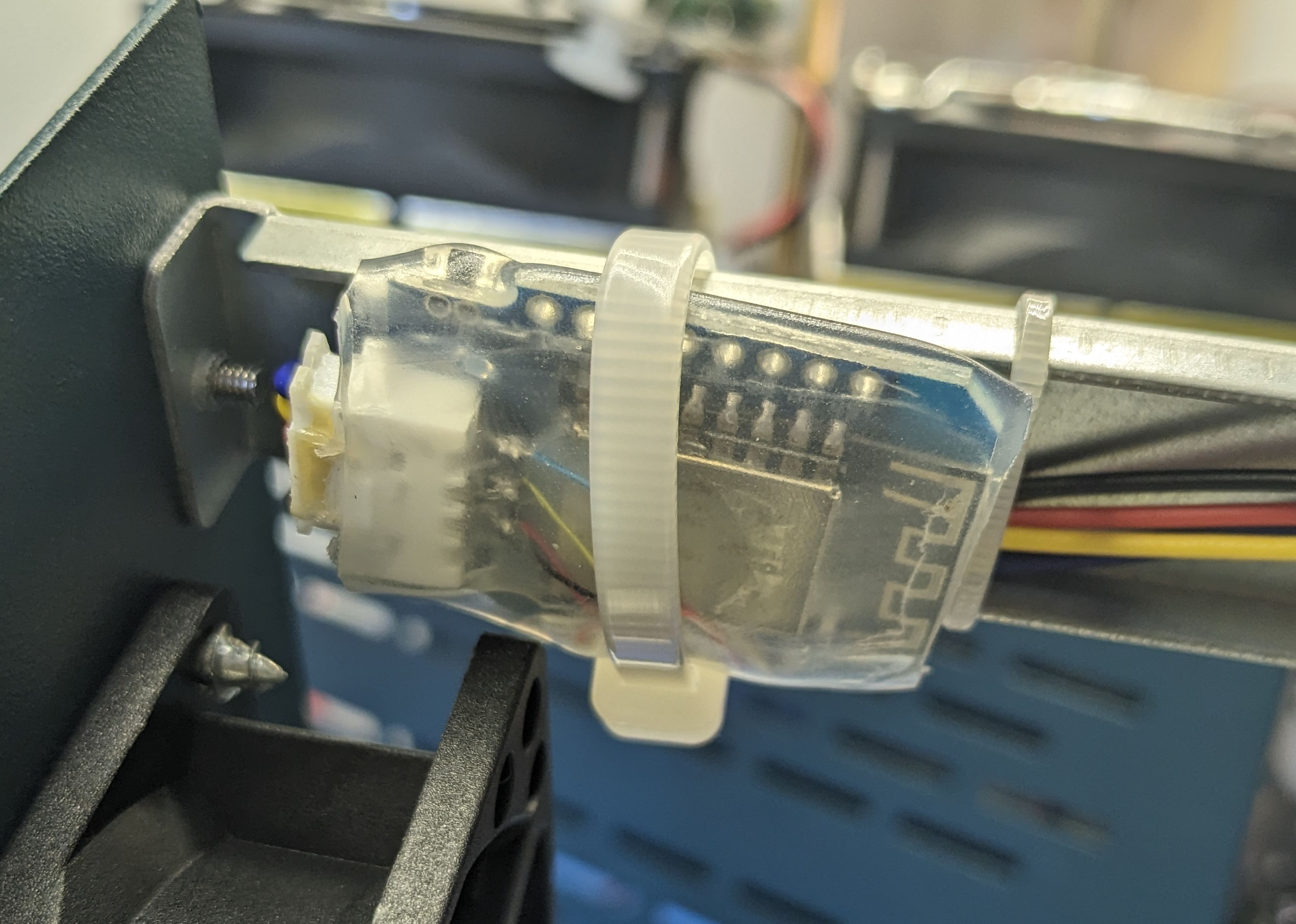
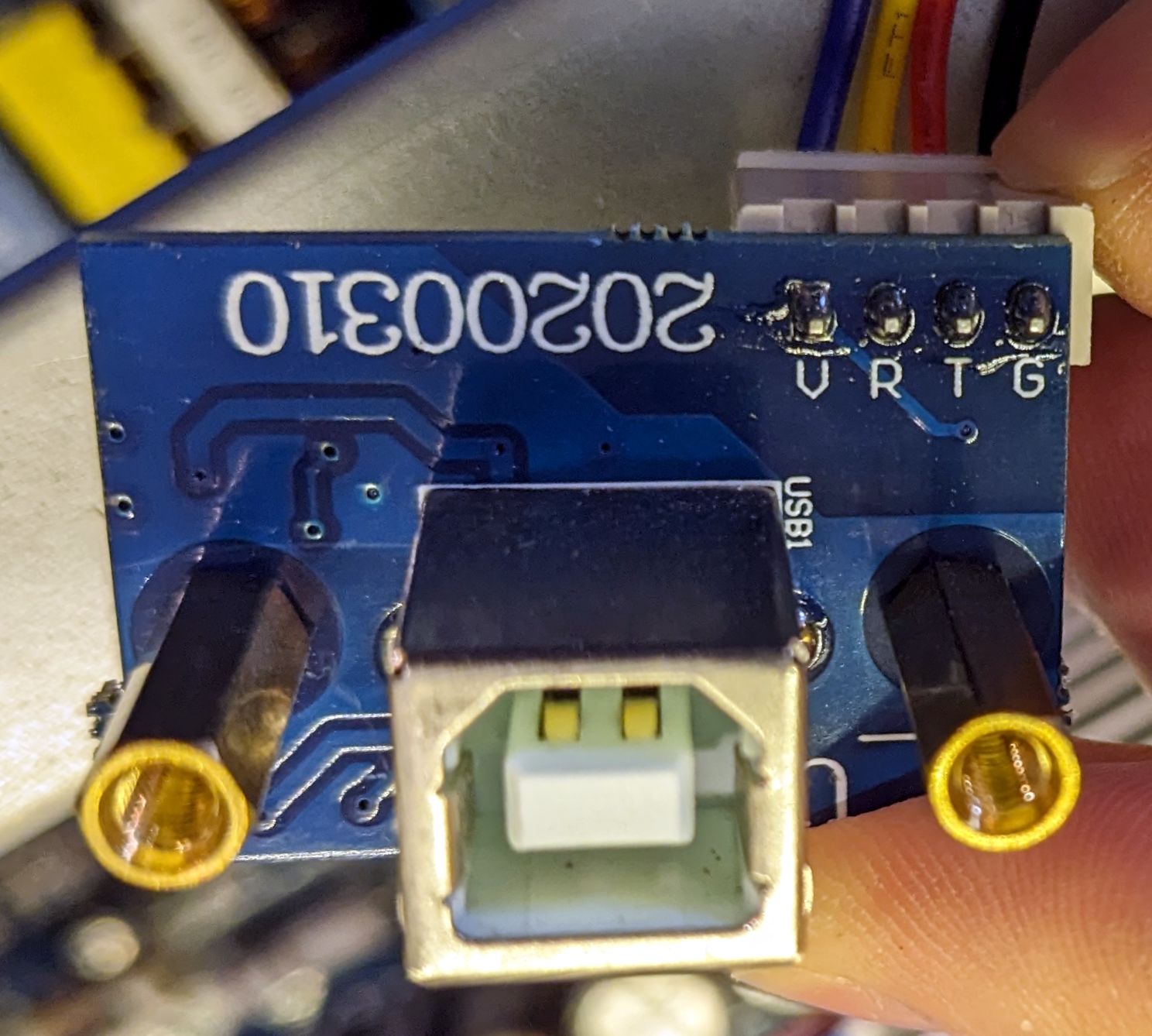
I then soldered the connector to the ESP8266 module, using the pinout on the stock USB adapter as a reference. As is often the case, RX goes to ESP8266 TX and vice versa.
The system was fully assembled and tested before I put everything back together with hot glue, heat shrink and cable ties.
Usage
Download the latest version of rs310p_dc_psu. I created a virtualenv with virtualenv venv, entered it with source venv/bin/activate, and installed the dependencies with pip install pymodbus==2.5.3 p3lib==1.1.10 bokeh==2.3.2.
I then started the GUI using ./psu.py -g -p <my-esplink-ip>:23, replacing <my-esplink-ip> with the actual IP. Once the GUI was running, I clicked the “On” button, and the power supply turned on.
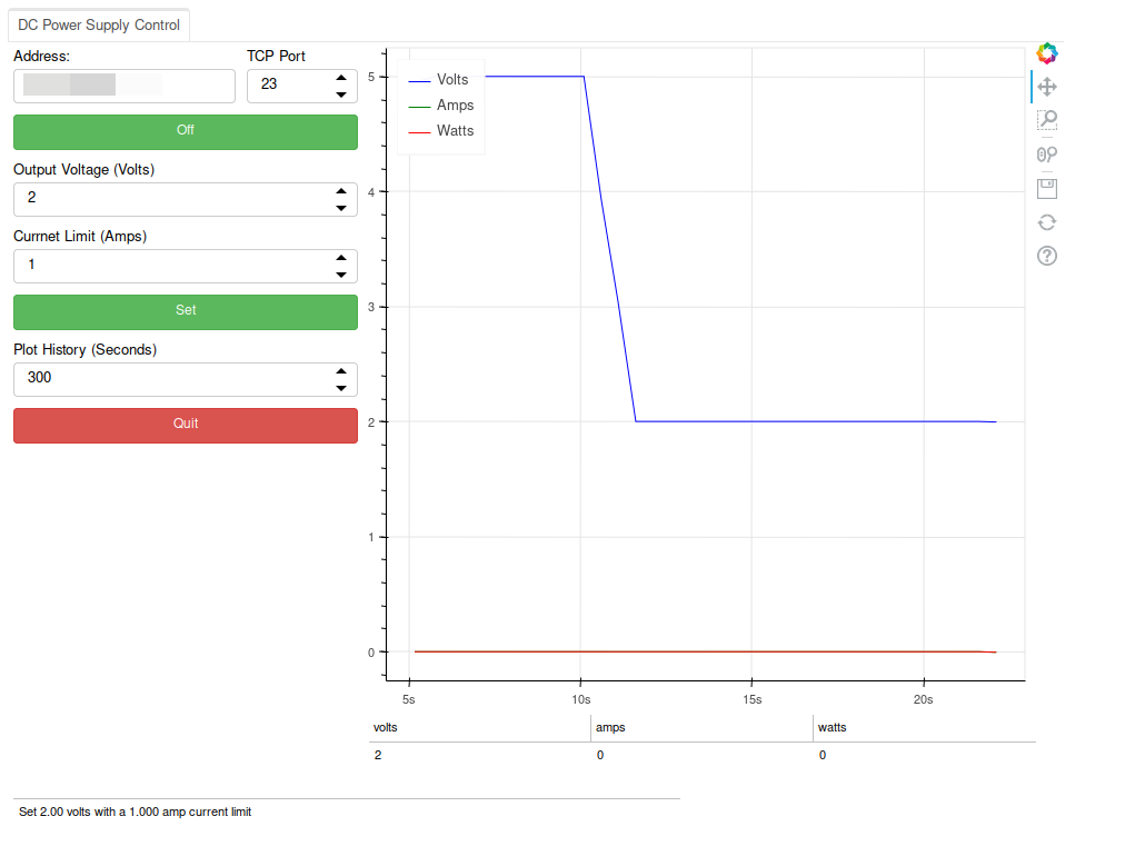
There’s lots of additional functionality in rs310p_dc_psu, see that project’s README for more information.