Introduction
Many packages don’t have KiCad footprints, and KiCad’s system doesn’t exactly make it the easiest to create create footprints from a drawing.
However, there’s another open-source tool that makes creating properly dimensioned polygons easy, and that’s FreeCAD.
Importing drawing
The first step in the process is to get the drawing from the datasheet and into FreeCAD, where you can then sketch over it.
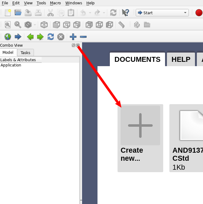
So, grab a screenshot of the drawing, and create a new FreeCAD file.
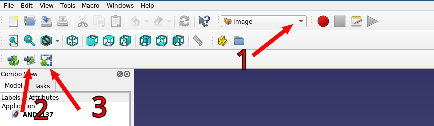
Then, switch into Image mode (1), and import the image (2). Select the image from your filesytem.
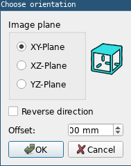
The default settings on the “Choose orientation” dialog are fine.
Then, we need to re-scale the image in order to get it to scale, so that we save some work later when we add dimensions. Press the “Scale image” button (3), and draw the red line across the largest dimensioned line in the drawing.
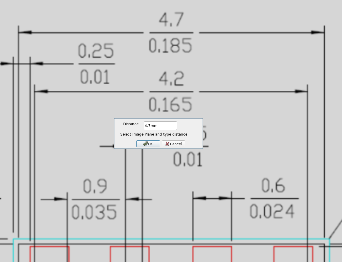
Once you’ve drawn the thin red line across the drawing, enter the length of the line into the dialog that comes up and press Ok. You may be prompted to “Select ImagePlane”. In that case, just click on the “ImagePlane” icon in the “Model” left side-pane.
Sketching the footprint

Enter “Sketcher” mode (2) in order to draw the footprint. Then create a new sketch (2), accepting the default options for the orientation.
Use the background image as your guide as you copy the lines from the drawing into FreeCAD. If you’re not familiar with how FreeCAD’s sketcher mode looks, take a look at this excellent video tutorial on the basics.
There’s a couple things that you must do for the remainder of this process to go smoothly:
- Do not use anything but lines. No circles, no beizers, etc.
- All lines must be drawn end-to-end, and in order. This also means you can only have a single shape, and it must be closed. If you need multiple shapes, use a separate sketch and follow the steps below multiple times.
- Make sure that your sketch is exactly centered. If you don’t do this, you will have issues aligning the pad in KiCad.
Getting data out of FreeCAD
You’ll need to open up the “Python console” by navigating to “View” → “Panels” → “Python console”. Then, while you’re still in sketch mode, paste the following code to get the list of points in the sketch:
" ".join([("(xy " + " ".join([str(round(v, 3)) for v in line.StartPoint][0:2]) + ") ") for line in ActiveSketch.Geometry if not line.Construction])
This will give you a string, which you will use later to import the data into KiCad.
Importing into KiCad
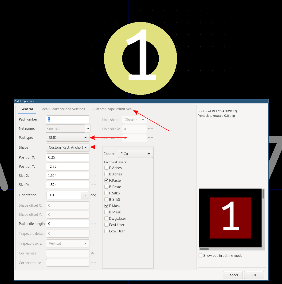
Set up the pad that you’ll be creating in KiCad. Create a new Pad with the “Pad type” set to “SMD”, and the “Shape” to “Custom (Rect. Anchor)”. Navigate to the “Custom Shape Primitives” tab.

Then press “Add Primitive”, and add a new “Polygon” primitive.
There’s a couple ways to import this into KiCad: either each point can be entered manually into the pad polygon dialog, or the footprint file can be modified in a text editor.
Manually type it in
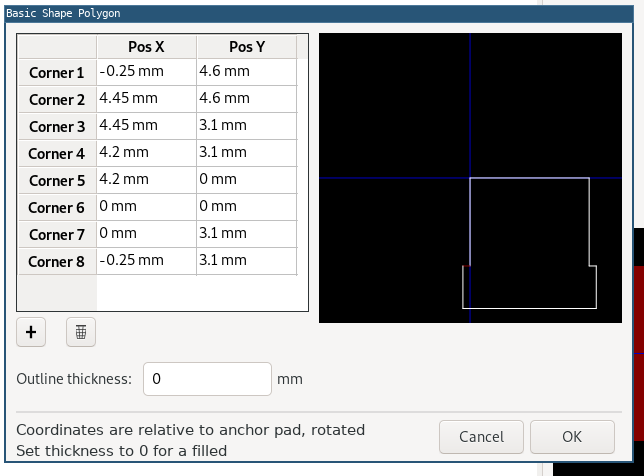
If you only have a few points, the easiest solution would be to just type in the points. This will work just fine, but isn’t practical once you reach a certain number of points.
Modify the footprint file
If you have more than a few points, you’ll want to create the “Polygon” shape, as shown above, and then type in three dummy coordinates.
Save the footprint and exit the footprint editor.
Open up the .kicad_mod file in a proper programmer’s text editor. Notepad or Microsoft Word will not work. Some examples of acceptable editors would be Notepad++, Visual Studio Code, Sublime Text, Gedit, or Vim.
Find the section in the file that looks something like this:
(pad 3 smd custom (at 1.5 0 90) (size 1.524 1.524) (layers F.Cu F.Mask)
  (zone_connect 2)
  (options (clearance outline) (anchor rect))
  (primitives
    (gr_poly (pts
      (xy -0.33 1.8) (xy -0.94 1.8) (xy -0.94 1.081))
    (width 0))
  ))
Your indentation may be different, but this is okay, since spaces and newlines are just ignored.
Replace the values in (pts with the values that you got in the FreeCAD Python console, so that it looks something like this:
(pad 3 smd custom (at 1.5 0 90) (size 1.524 1.524) (layers F.Cu F.Mask)
  (zone_connect 2)
  (options (clearance outline) (anchor rect))
  (primitives
    (gr_poly (pts
      (xy -0.33 1.8) (xy -0.94 1.8) (xy -0.94 1.081) (xy -1.6 1.081) (xy -1.6 1.8) (xy -2.21 1.8) (xy -2.21 0.78) (xy -2.05 0.78) (xy -2.05 0.485) (xy -2.805 0.485) (xy -2.805 -0.115) (xy -2.05 -0.115) (xy -2.05 -1.94) (xy -2.805 -1.94) (xy -2.805 -2.54) (xy -2.05 -2.54) (xy -2.05 -2.72) (xy 0 -2.72) (xy 2.05 -2.72) (xy 2.05 -2.54) (xy 2.805 -2.54) (xy 2.805 -1.94) (xy 2.05 -1.94) (xy 2.05 -0.115) (xy 2.805 -0.115) (xy 2.805 0.485) (xy 2.05 0.485) (xy 2.05 0.78) (xy 2.21 0.78) (xy 2.21 1.8)(xy 1.6 1.8) (xy 1.6 1.081) (xy 0.94 1.081) (xy 0.94 1.8) (xy 0.33 1.8) (xy 0.33 1.081) (xy 0 1.081) (xy -0.33 1.081) (xy -0.33 1.8))
    (width 0))
  ))
Save the file, and you’re done!