LED Grow Light Teardown

Feb 08, 2020
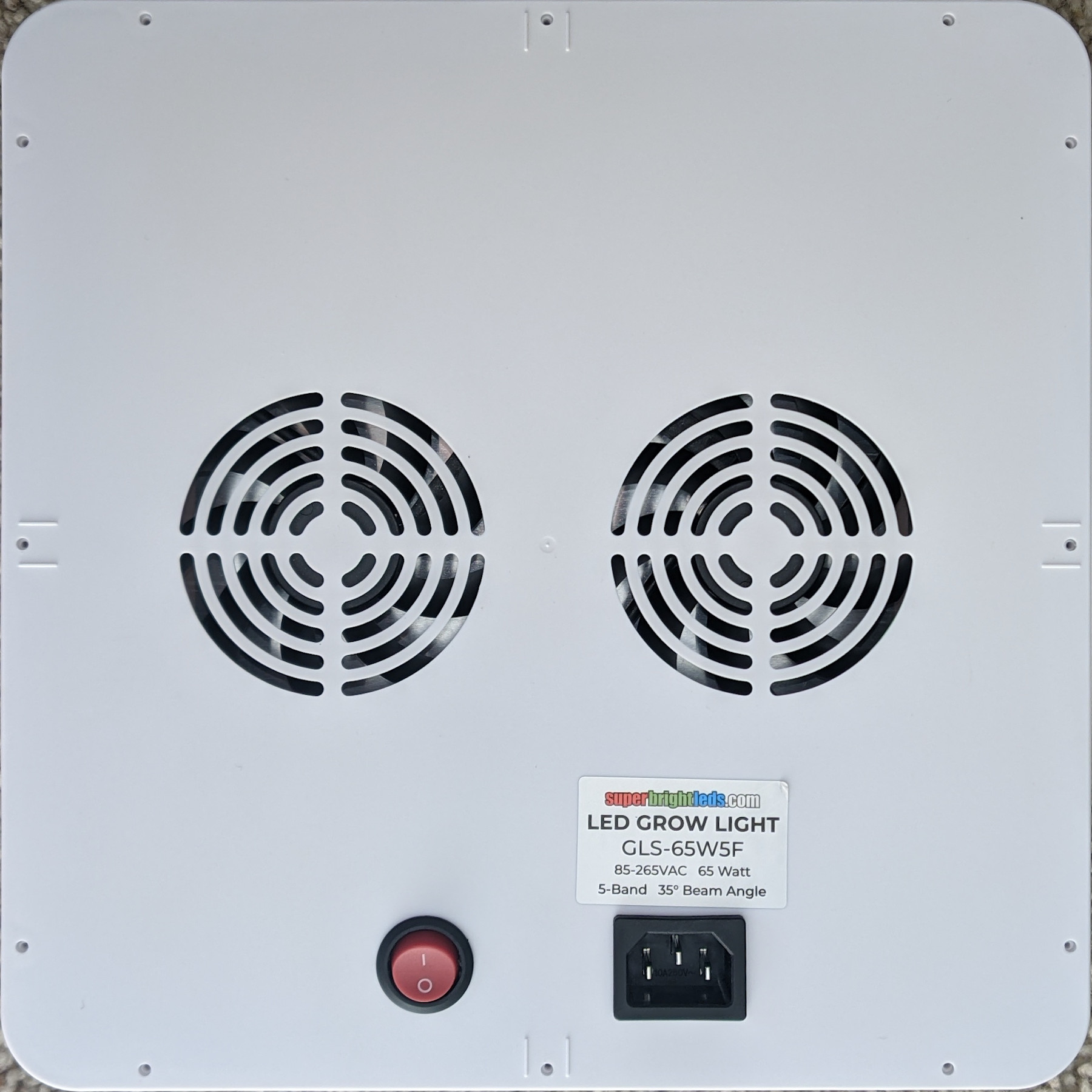
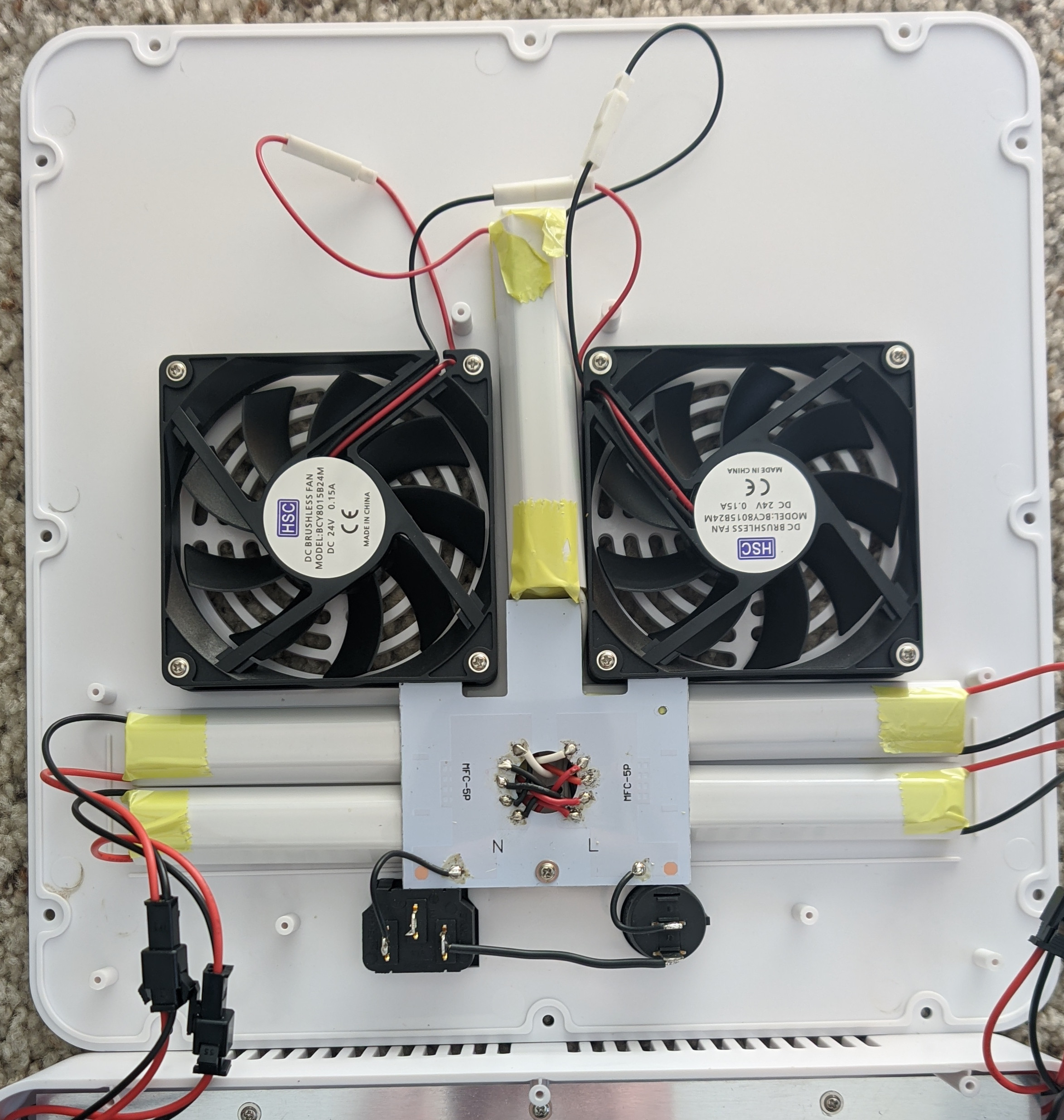
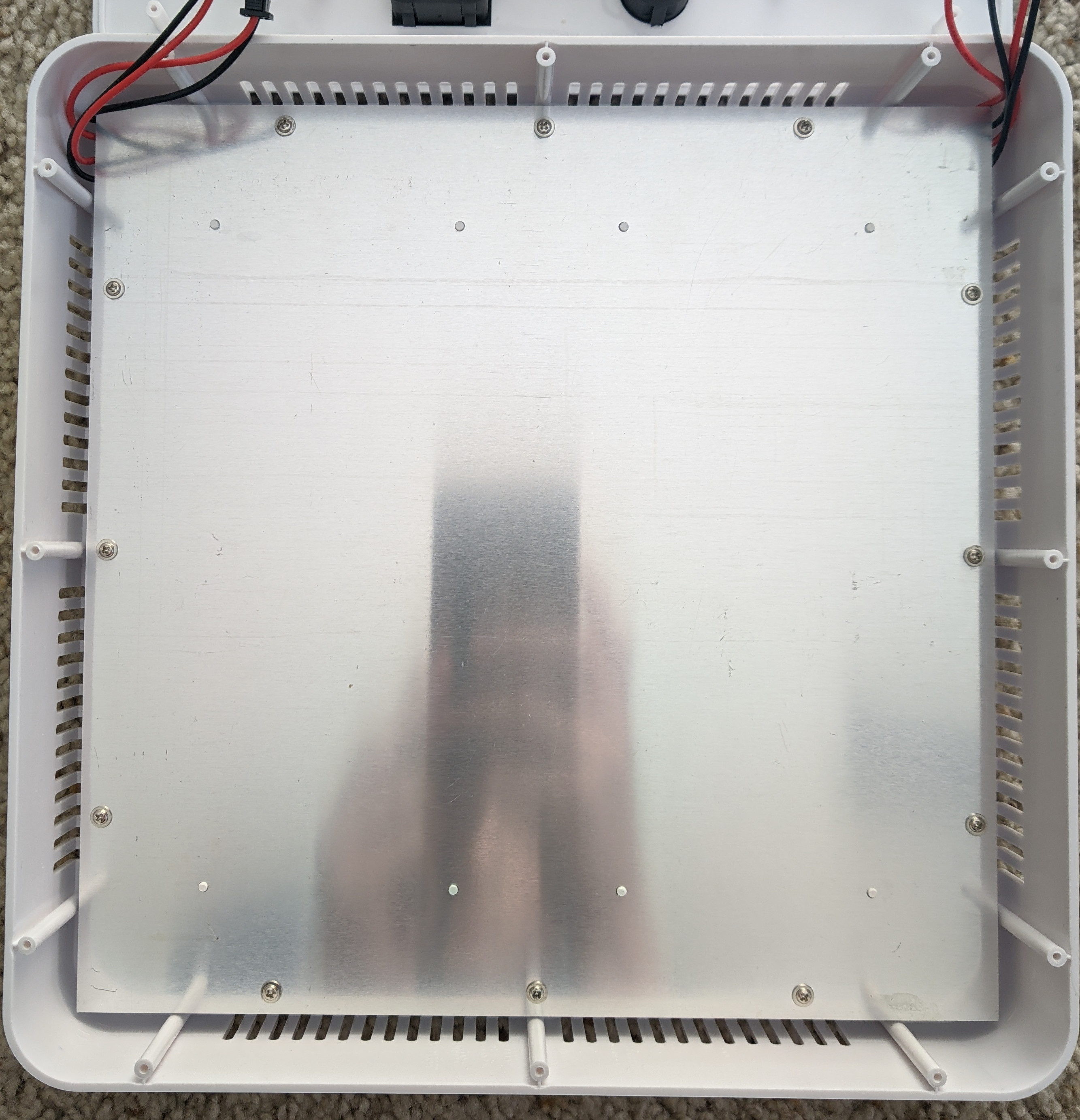
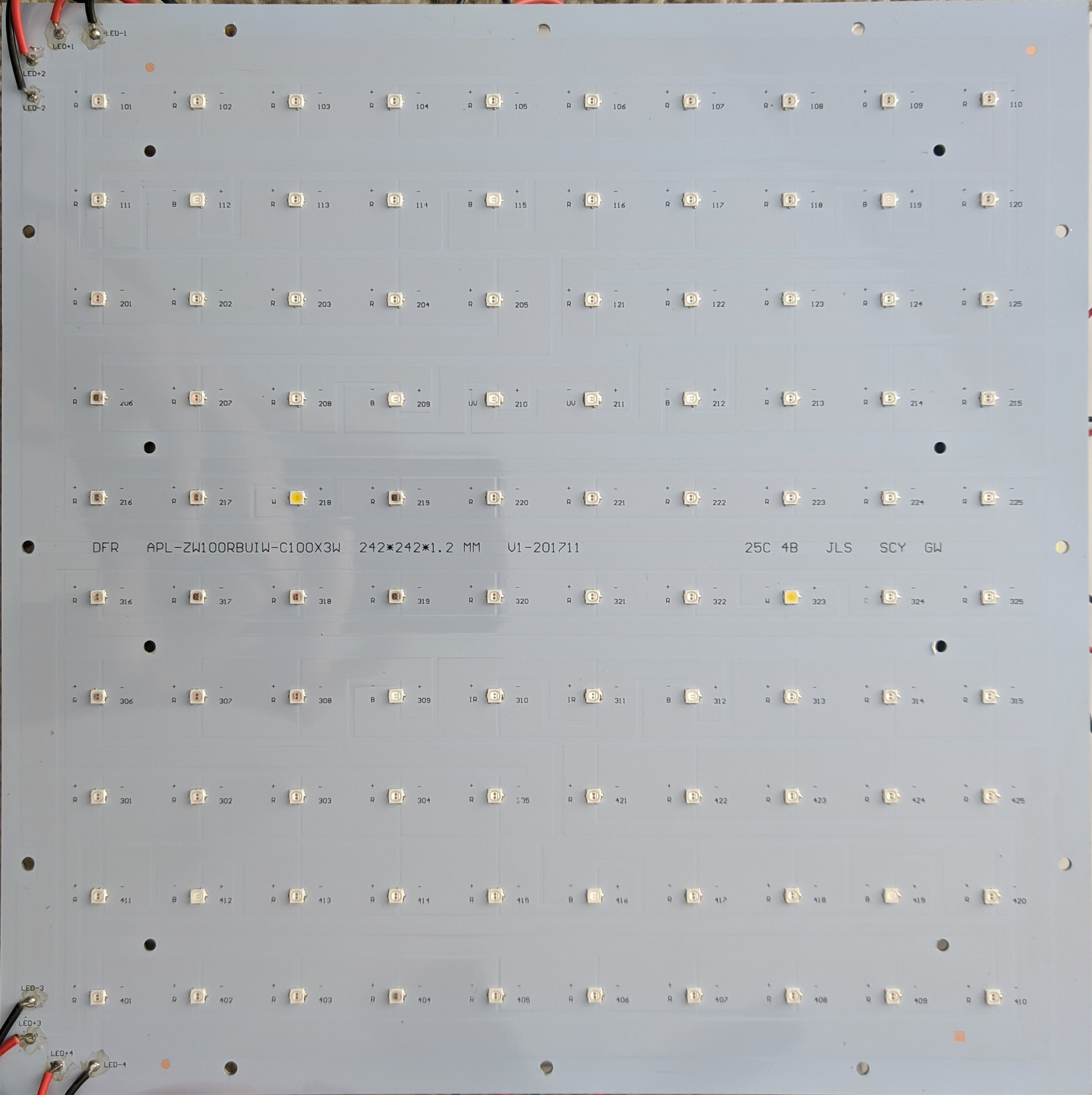
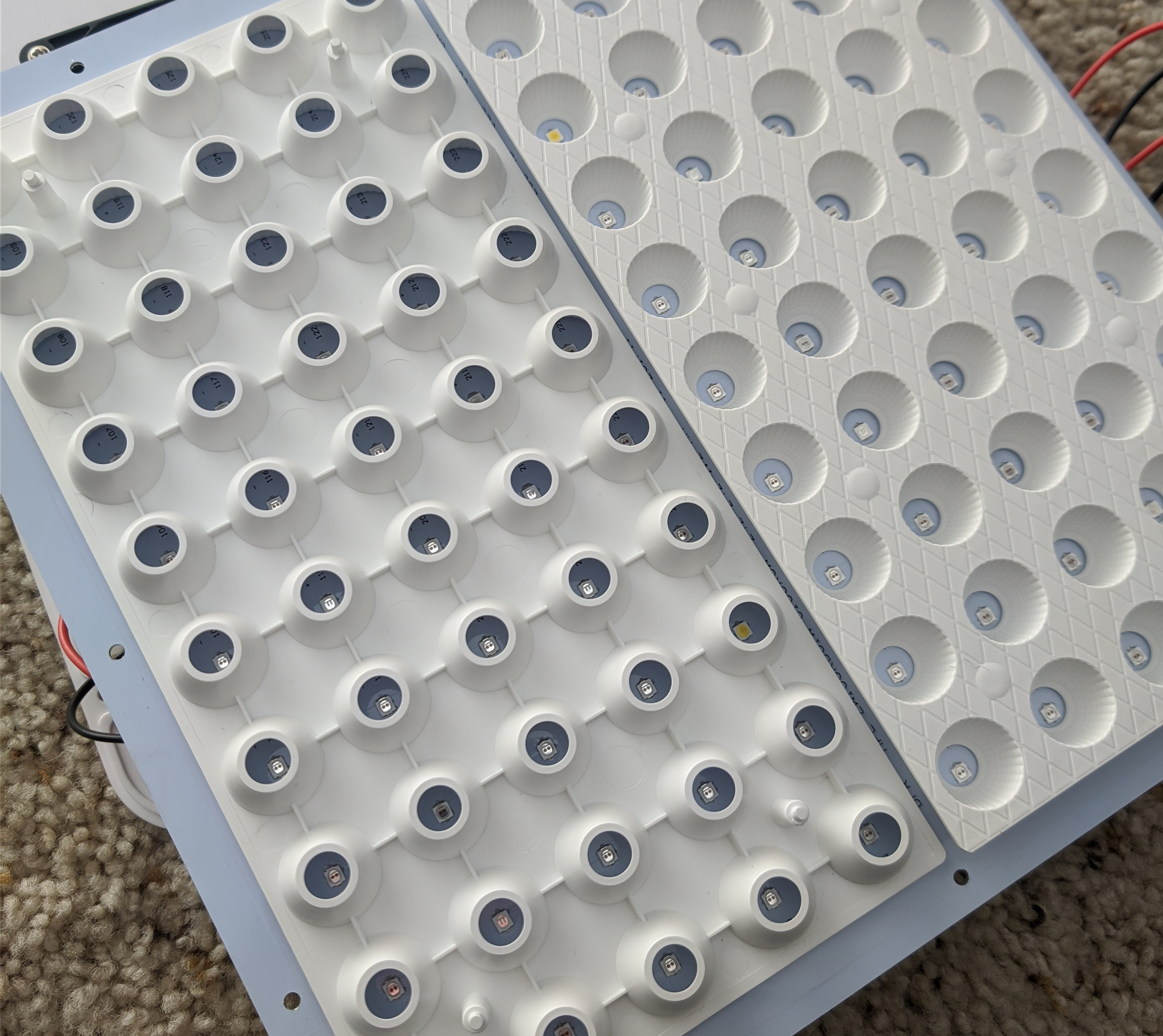
The rear of the GLS-54W5F grow light from superbrightleds.com.
The inside of the back cover, where all the electronics are. There are 4 constant-current power supplies for the LEDs, and another constant-current (115mA) power supply for the fans. The fans are two 80×80×15mm fans, 24V, 150mA, wired in serial. The aluminum circuit board is cleverly designed to wedge in under the fan lip and apply pressure on the power supply cases in order to keep everything in place.
The rear of the LED PCB. It's an aluminum PCB for better heatsinking.
The front of the LED PCB. Each constant-current power supply is attached to 24 LEDs in series.
The construction of the reflectors on the other side of the board. I'm not certain what the point of these is, since the light would function exactly the same without them.

Fan Power Supply

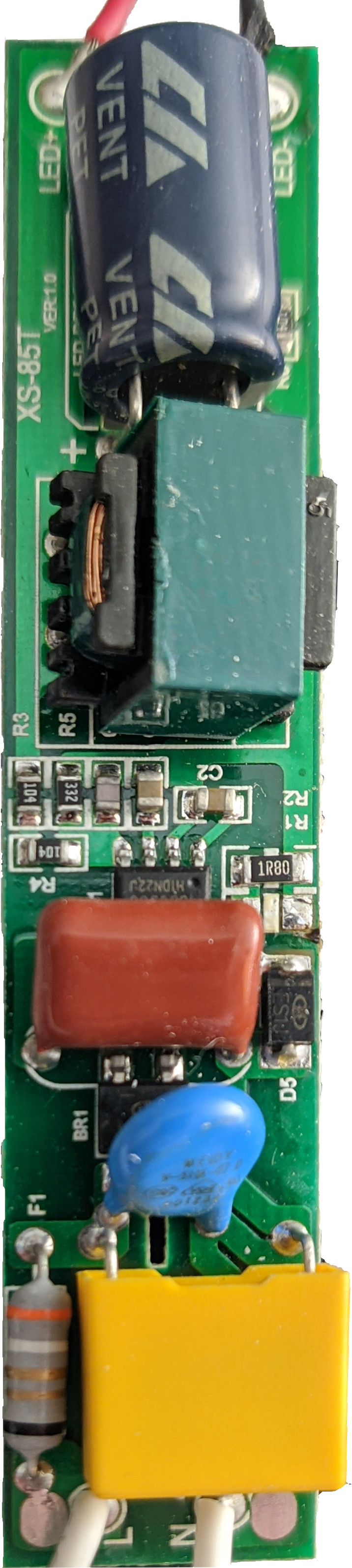
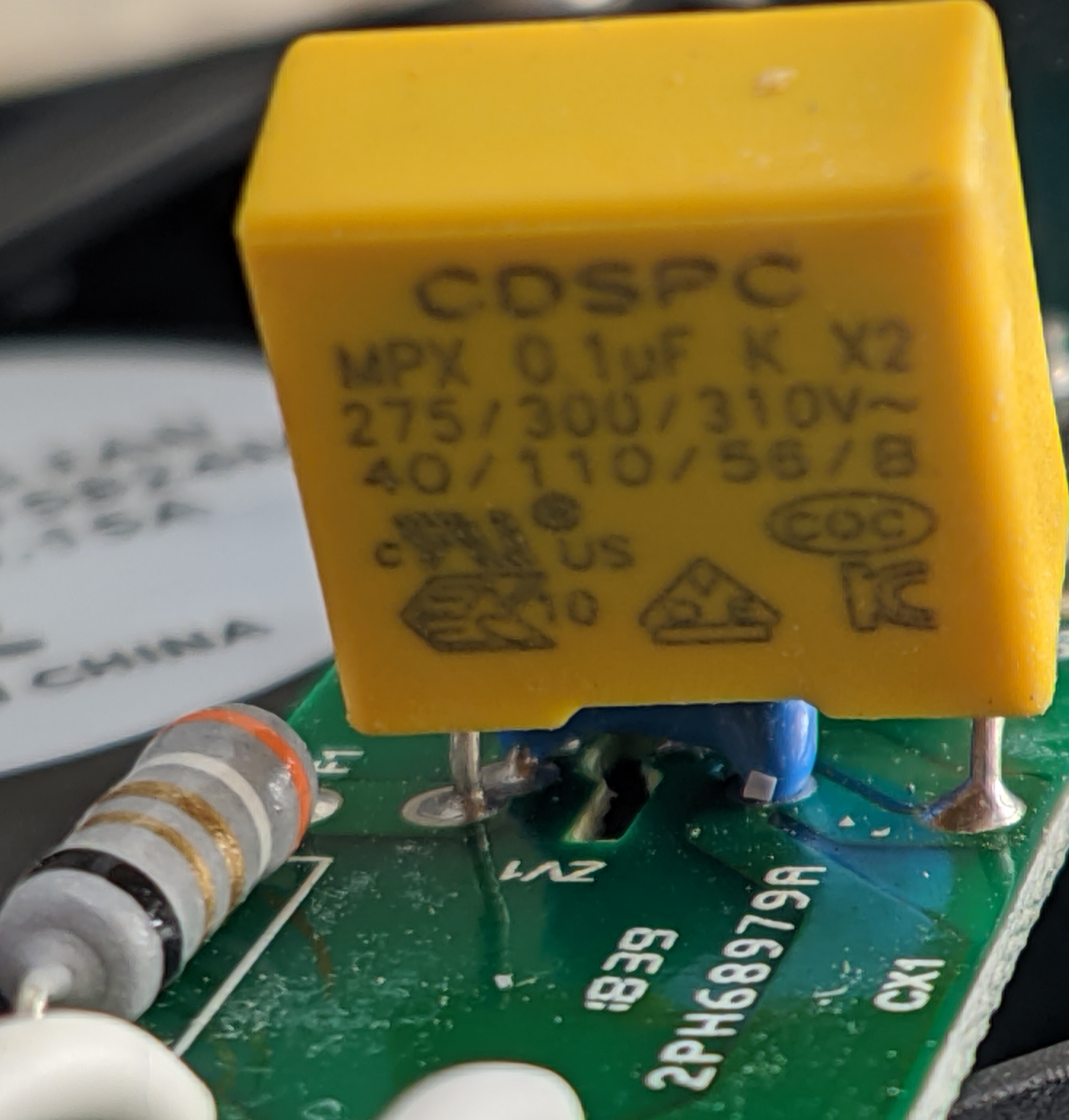
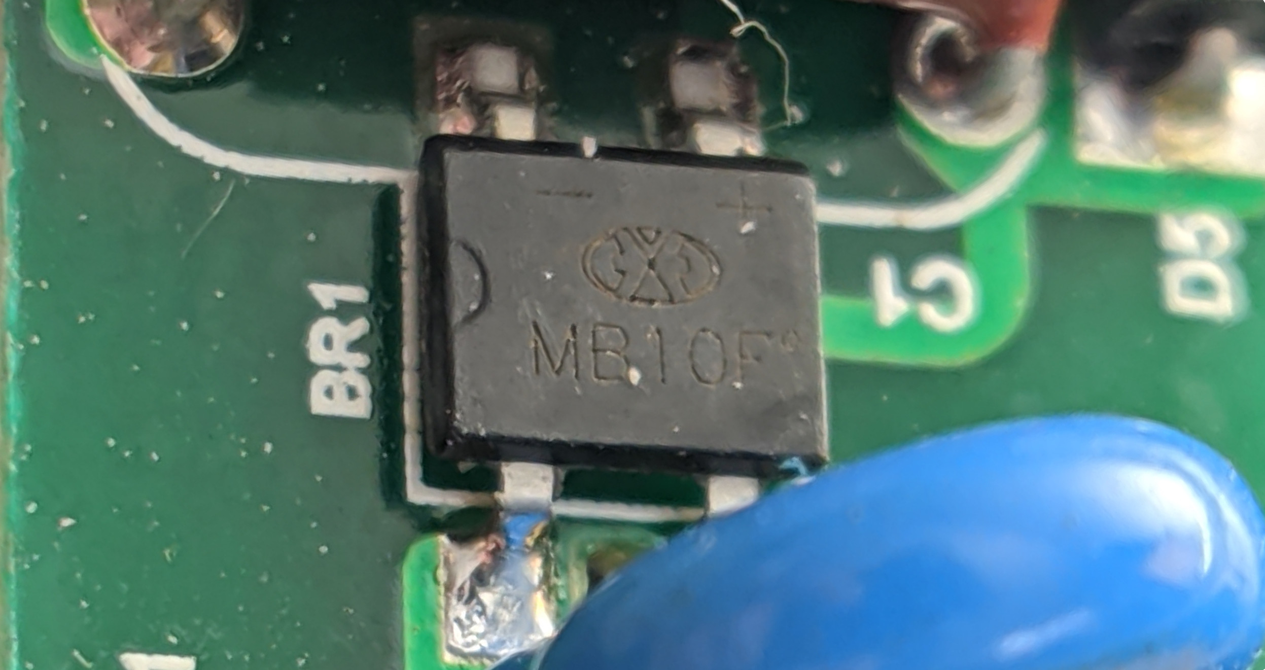
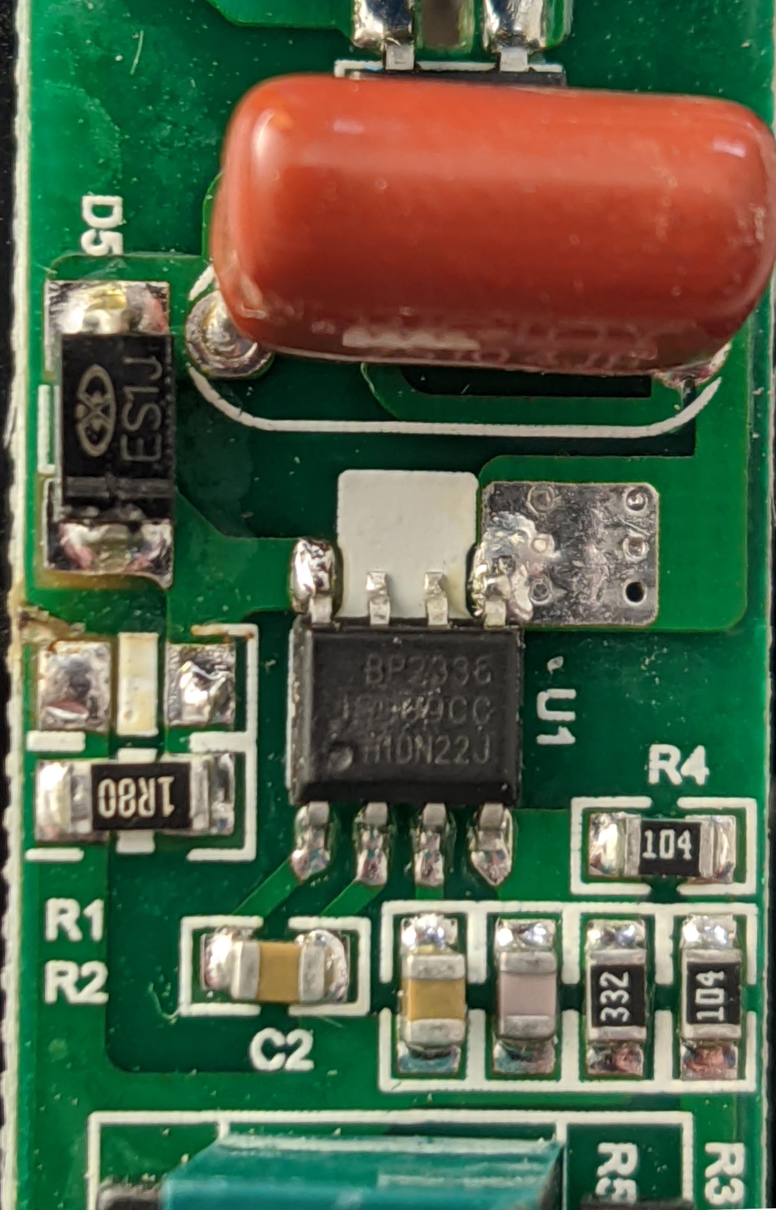
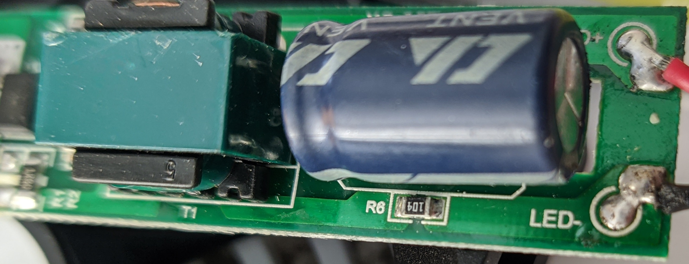
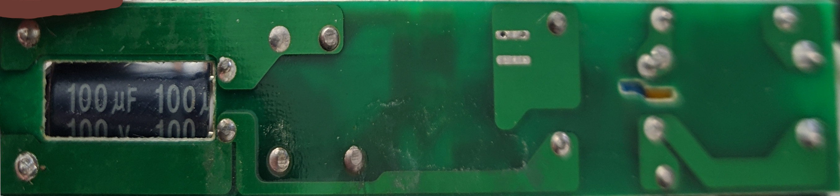
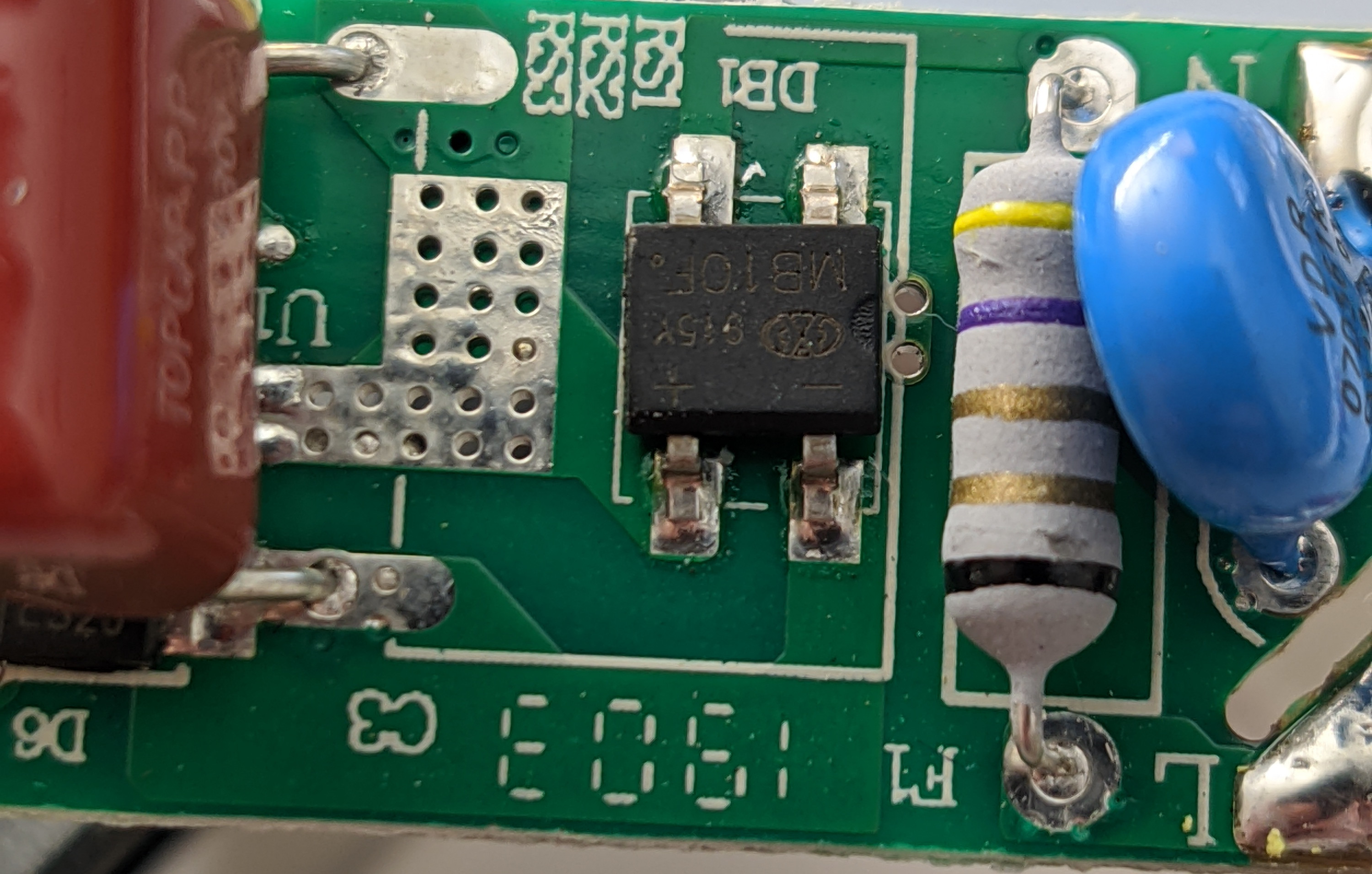
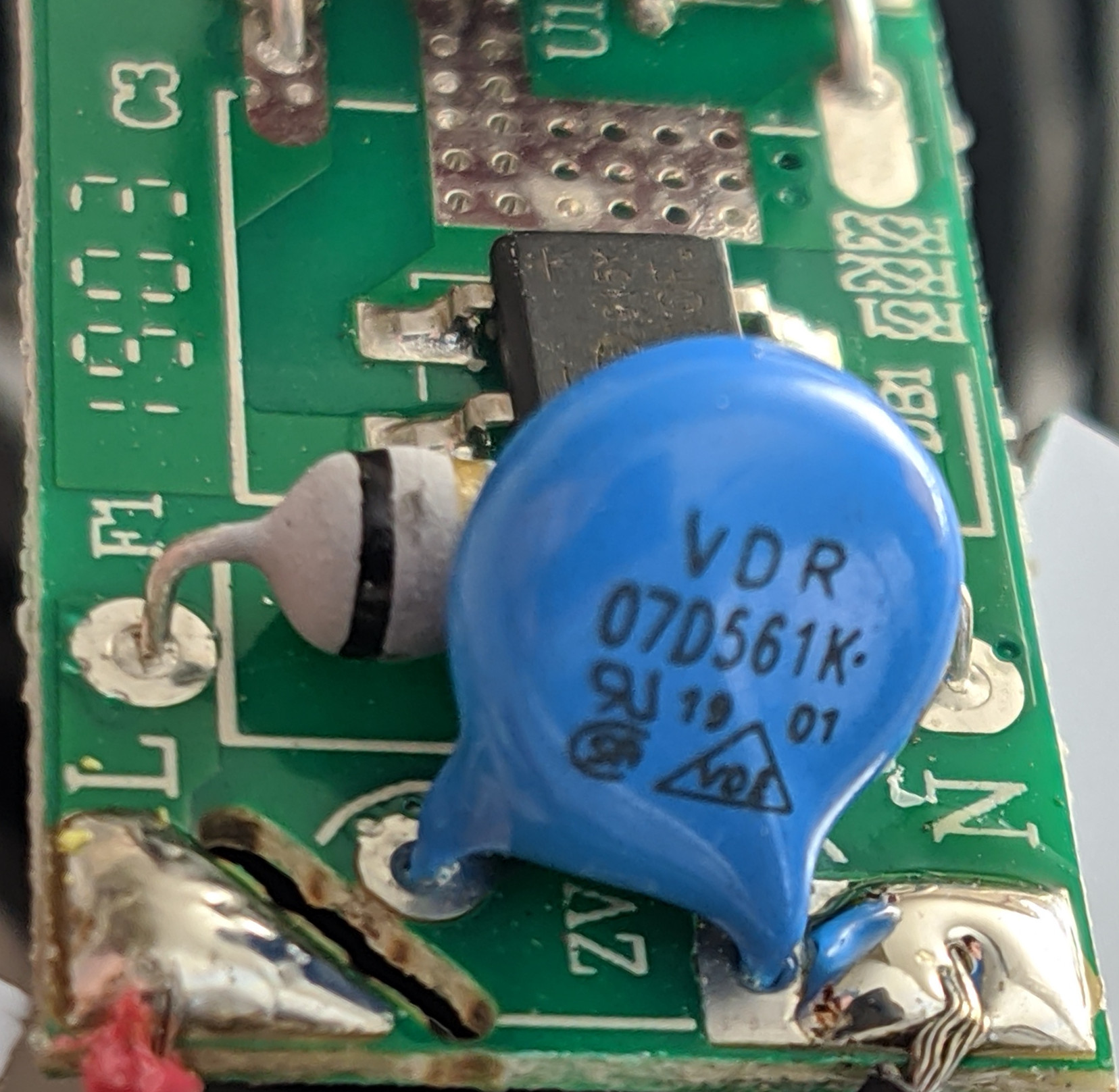
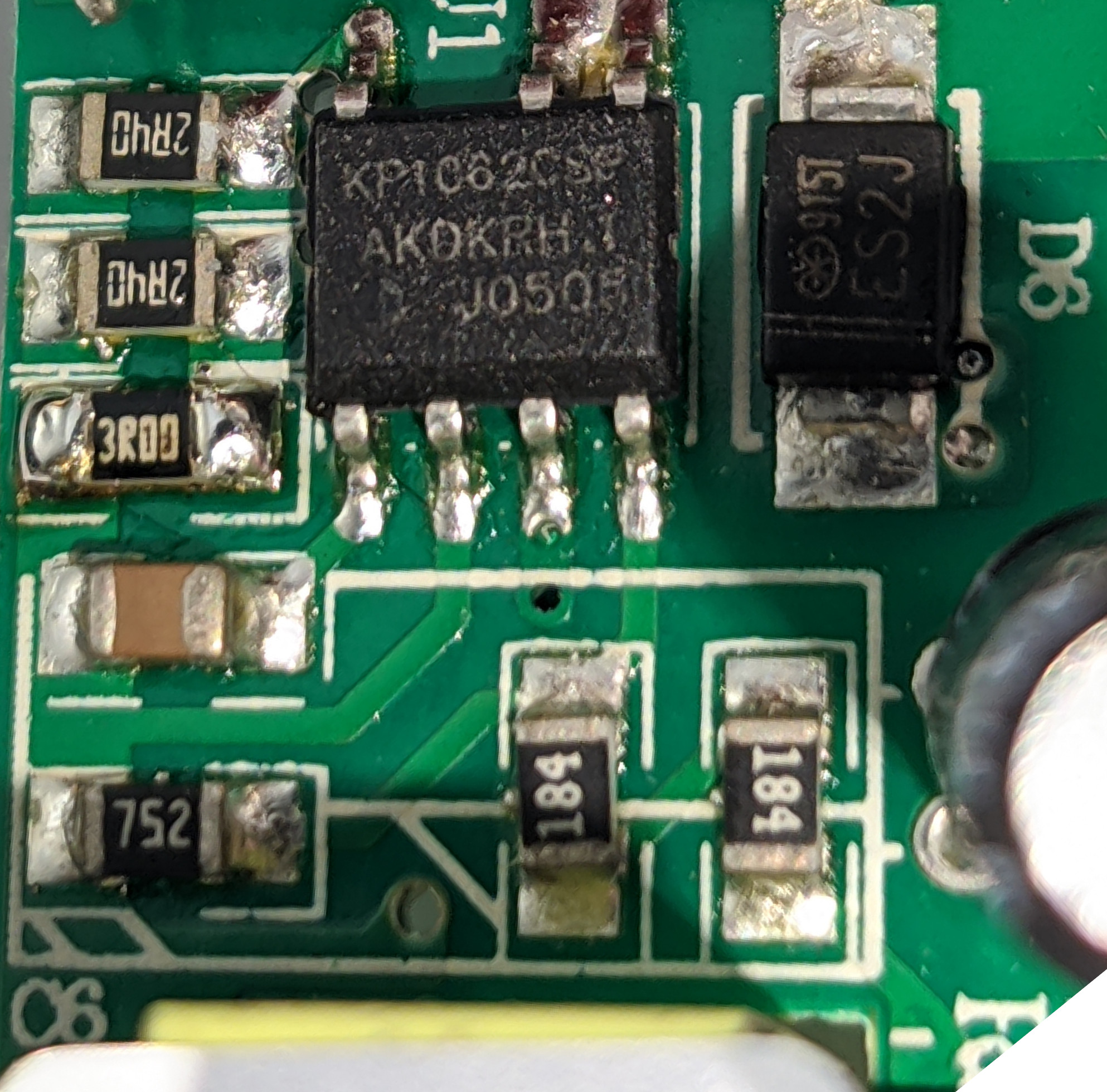
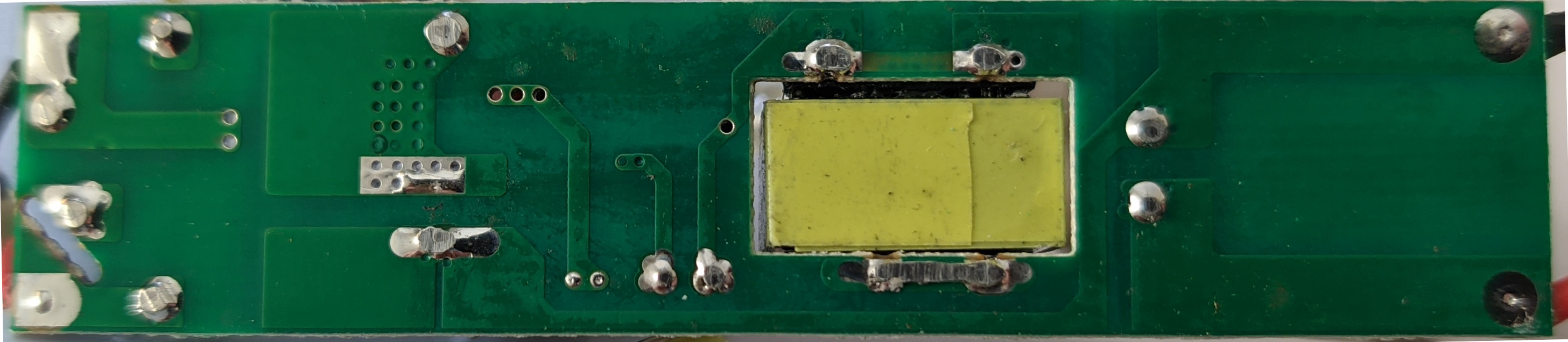
The circuit board for the fan constant-current power supply. This is a non-isolated power supply, and will go all the way up to line voltage if there is no load.
The input filtering section, featuring the MOV (blue), pre-rectification capacitor (yellow), fuse (F1), and post-rectification capacitor (red).
The X2 input filtering capacitor (yellow), and the fuse (F1).
The BM10F full bridge rectifier.
The <a href='/assets/files/2020-02-08-grow-light-teardown/BP2338J.pdf'>Bright Power Semiconductor Co. BP2338J</a> constant-current LED driver. Pins 6 & 7 are not connected--it's unclear why this was done, but pins 8 & 7 and 5 & 6 are connected internally to the chip. You can also observe the current measurement: R2=1.8Ω, Vref=0.2V, and therefore the output current is Vref/R2=111mA. This matches the observed output current.
The Bright Power Semiconductor Co. BP2338J constant-current LED driver. Pins 6 & 7 are not connected--it's unclear why this was done, but pins 8 & 7 and 5 & 6 are connected internally to the chip. You can also observe the current measurement: R2=1.8Ω, Vref=0.2V, and therefore the output current is Vref/R2=111mA. This matches the observed output current.
The output inductor and filtering capacitor. The transformer provides no isolation here.
The bottom of the board. Note the 100uF, 100V output capacitor: this will cause problems in open-circuit situations where the output voltage will be equal to line voltage (120V or 250V).

LED Power Supply

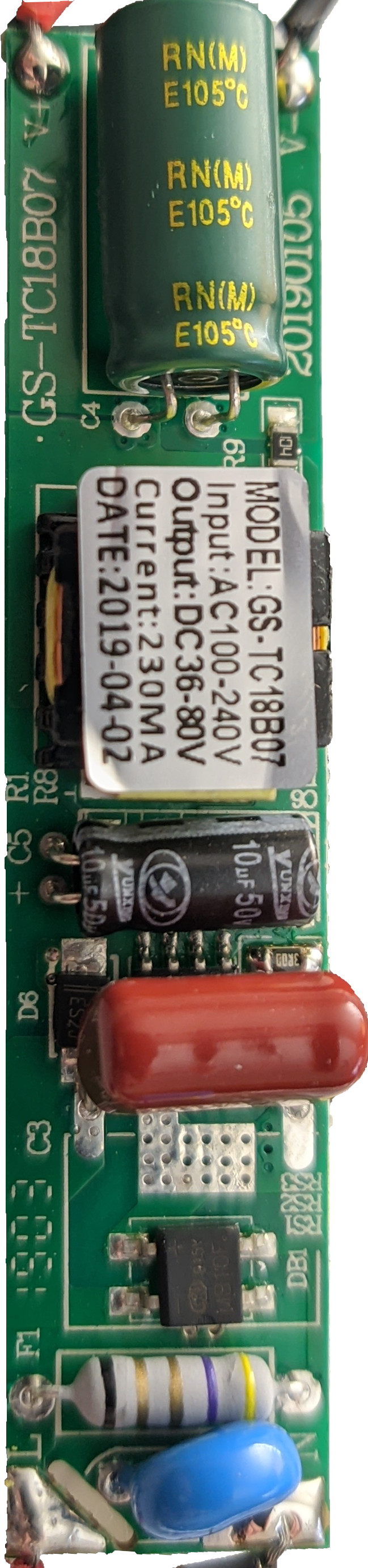
Each of the 4 LED CC power supplies are identical and output 230mA each.
The MB10F full-bridge rectifier, as well as the fuse (F1) and input filtering capacitor (C3, red).
The VDR 07D561K MOV (blue).
This power supply makes use of the <a href='/assets/files/2020-02-08-grow-light-teardown/Kiwi-KP1062C.pdf'>Kiwi Instrument Corporation KP1062</a> constant-current LED driver.
This power supply makes use of the Kiwi Instrument Corporation KP1062 constant-current LED driver.
The 100V, 68uF output filtering capacitor.
The bottom side of the power supply. Note that two transformer pins are tied together: it is being used as an non-isolated inductor, and was likely chosen over a regular inductor for cost reasons.