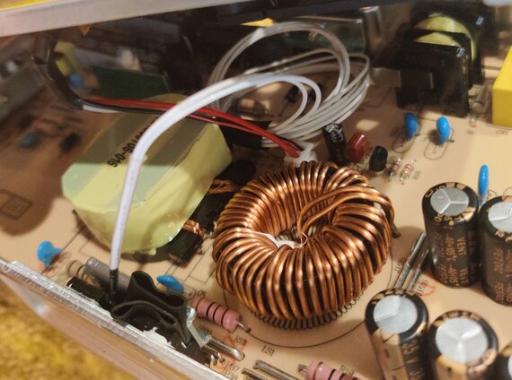
The Ender 5 contains a Landy LRS-350-24. This PSU is clearly a poorly-made and unlisted clone of the MEAN WELL LRS-350-24.
It is a flyback power converter, using SMF18N50s as the mains-side switches, and MBR20200 diodes as the output-side switches. The output-side diodes are marked DS1 and DS2.
For the MBR20200, the relevant characteristics are:
| Characteristic | Typ |
|---|---|
| Vf, forward voltage drop | 0.9V |
| Tj, operating junction temperature | 150°C |
For the SMF18N50, the relevant characteristics are:
| Characteristic | Typ |
|---|---|
| Rds(on), on resistance | 0.25Ω |
| Tj, operating junction temperature | 150°C |
Assuming 80% efficiency, the power dissipated over the mains-side MOSFETs is (80%×350W/110V)^2 × 0.25Ω = 1.6W.
Assuming 80% efficiency, the power dissipated over the output-side diodes is (80%×350W/24V) × 0.9V = 10.5W.
Therefore, we ought to put our temperature sensor on the output side. This is nice, because otherwise we would have needed to be very careful not the ruin our mains isolation.
We now need to control the fan speed such that it only reaches max speed when the parts get hot.
I found a BS170 in one of my parts bags, so putting that together like this:

I simulated this circuit with falstad.com/…, and it works, although the MOSFET does get toasty when the temperature is about 53°C.
This isn’t ideal, but:
- the 600mW dissipated at that point is less than the max 830mW for this part
- Vth actually decreases as the temperature increases
- we have a cooling fan reducing the thermal resistance
- hopefully we get lucky and our steady state temperature is either higher or lower than 53°C

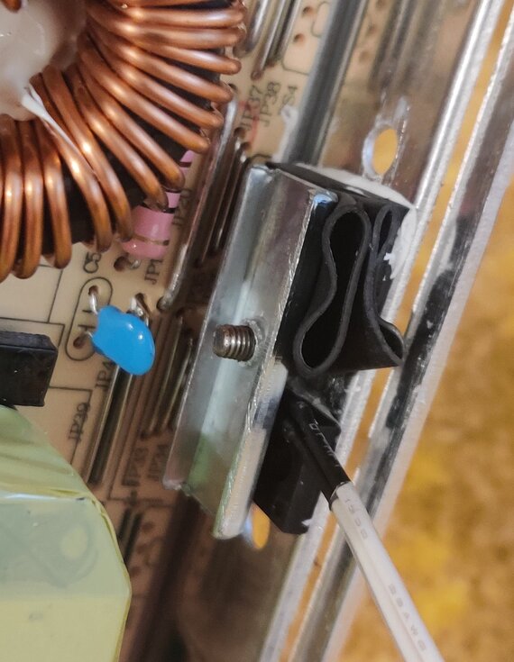
Securing the thermistor is tricky. The solution I arrived upon is to wrap the cable around the center screw on the output diodes, and bury the glass bead in the thermal paste in the diode screw hole. I then placed a folded piece of heat shrink to help secure the bead into the hole.
I’m comfortable with this because these diode packages are insulated. The metal tab is coated with plastic.

Everything is then wrapped up in insulating tape and taped out of the way. Unfortunately, there’s no good place to put the thermistor wire. A coil of wire in a SMPS is not a good idea. I’ll be redoing this at some point, with a PWM solution, and I’ll cut the wire shorter then.
