I hate loud fans, especially when there’s no good reason for them to be loud. Unfortunately, lots of equipment, especially that designed for industrial rather than household use, has permanently loud fans.
I’ve developed a tiny board that can be spliced into any fan wire to allow for control. It doesn’t require the fan to support PWM, and can be used with fans from 5 to 24V. The control algorithm is inspired by Matt’s trapezoid control algorithm, with my own improvements to overcome initial static friction. Here’s how it works:
- Measured temperature is 20°C, the fan starts in the off state
- Temperature increases to 35°C, and the fan is ramped to 100% for 200ms to overcome initial static friction.
- Fan speed is set linearly between the min-speed & 100% as the temperature varies over the temperature range
- Once the temperature falls under 27°C (8°C hysteresis is the default), the fan is shut off
Getting one
The firmware & kicad source files can be found in the repository: https://github.com/flaviut/fan-controller
You can get gerber files from the releases in the sidebar to get you own produced. Note that you will need a Tag-Connect TC2030-IDC-NL-10 & a SWD programmer to program the board. Once you’ve installed software dependencies (gcc for arm-none-eabi & pyocd), flashing is as simple as make flash in the firmware directory.
Materials
- populated circuit board
- PTC 3950 10kΩ thermistor
- wire cutters & strippers
- soldering iron
- solder
- Tag-Connect TC2030-IDC-NL-10
- SWD programmer
- wide heatshrink or 18650 battery wrap
Installation
Warning: This kind of equipment often has high voltage in the same enclosure. This is risky, and you should recognize that you are solely responsible for your safety & the safety of those using the modified equipment.
The first step is identifying where and how to mount the PTC thermistor. For the power supply I will be quieting here, I see that there’s a thermal fuse attached to this heatsink, so it is likely the hottest part. I will mount the thermistor here:
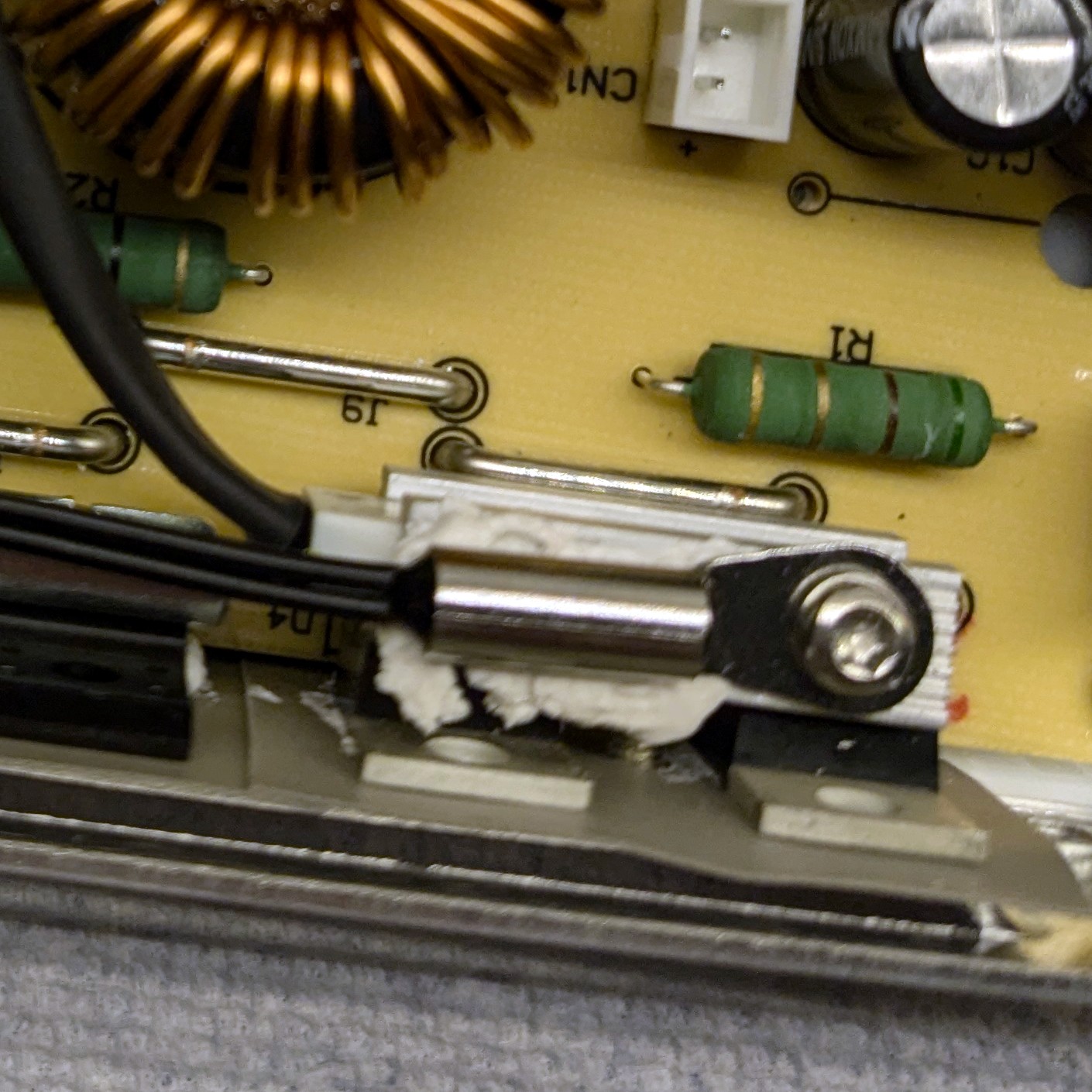
Every situation is unique. In this case, I drilled a hole in the aluminum heatsink, and used a standard M3 bolt to mount the thermistor. Because alumimum is soft, the bolt was able to tap it’s own threads. I also used a bit of thermal paste to improve thermal conductivity, although I’m skeptical it makes a difference.
The next step is to connect all the wires. This can be done using connectors, or the wires can be soldered directly to the board:
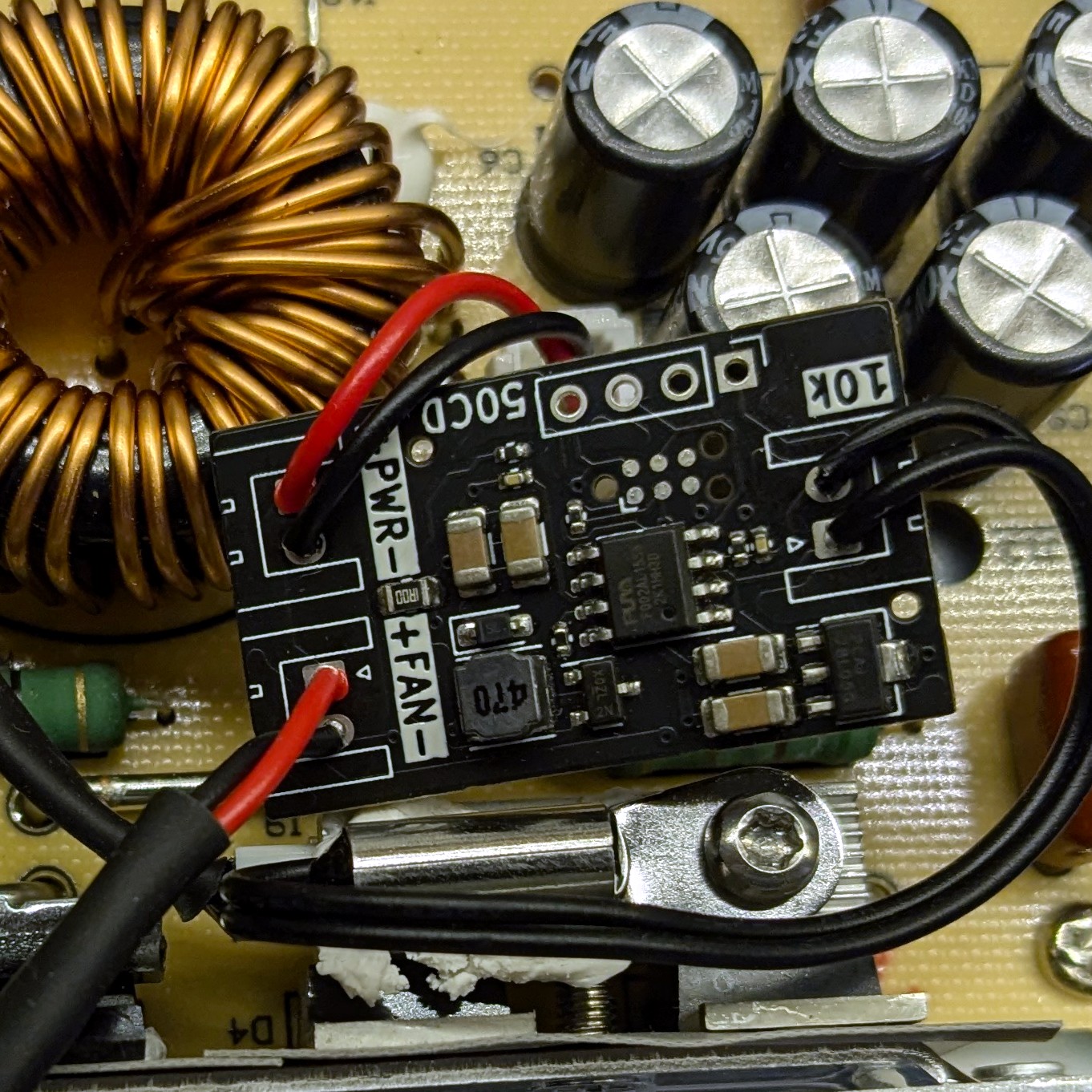
Note the additional heatshrink insulation on the fan wires. The heatshrink was originally there, and was kept because the fan is placed on the high-voltage side of the power supply. This heat shrink must be kept, because it acts as a second layer of insulation from high voltage.
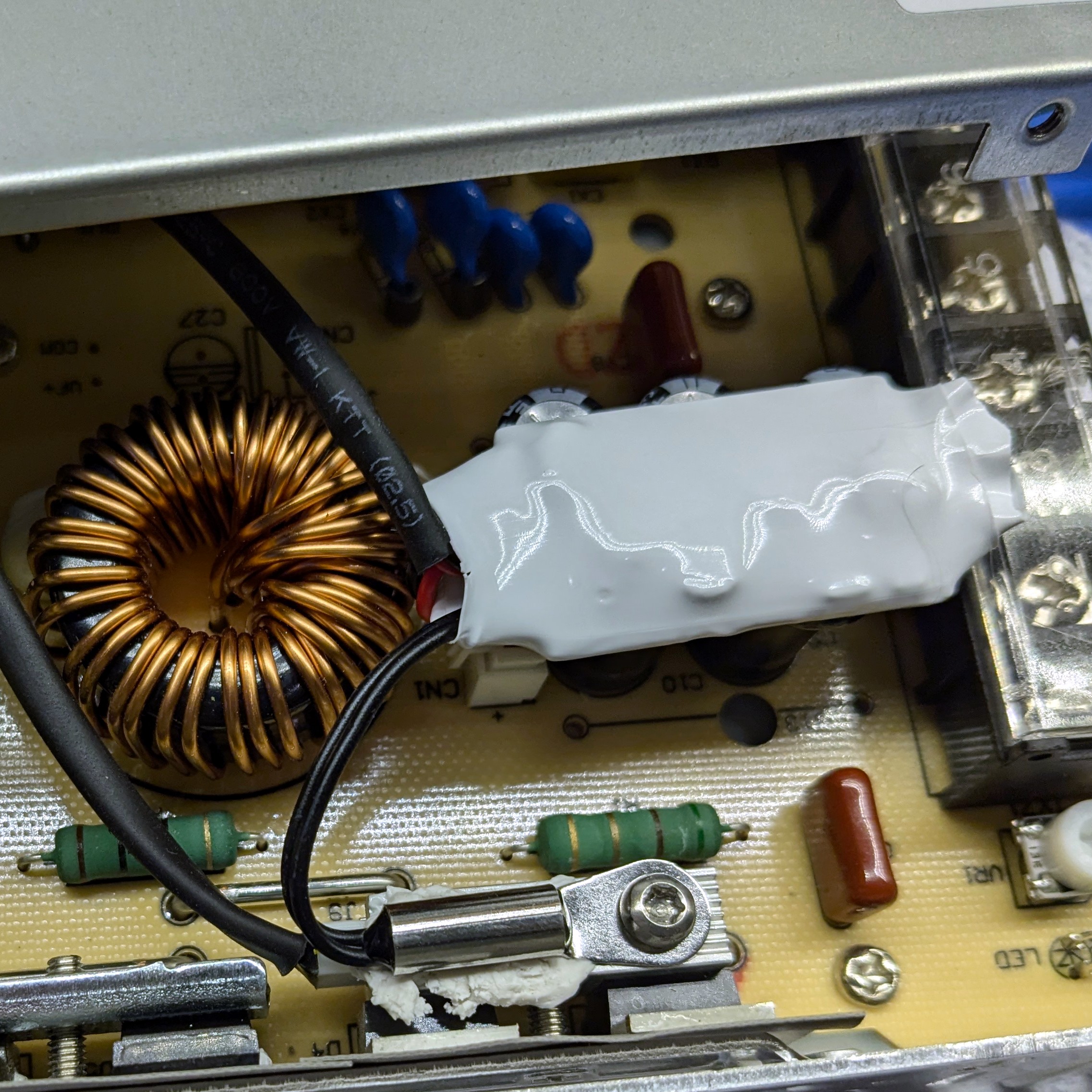
Once everything was soldered in place & connected, a dab of hot glue was placed on each connection to act as strain relief and prevent wire shorts from vibration. Then two layers of 18650 battery wrap were applied to insulate the module from the rest of the electronics.
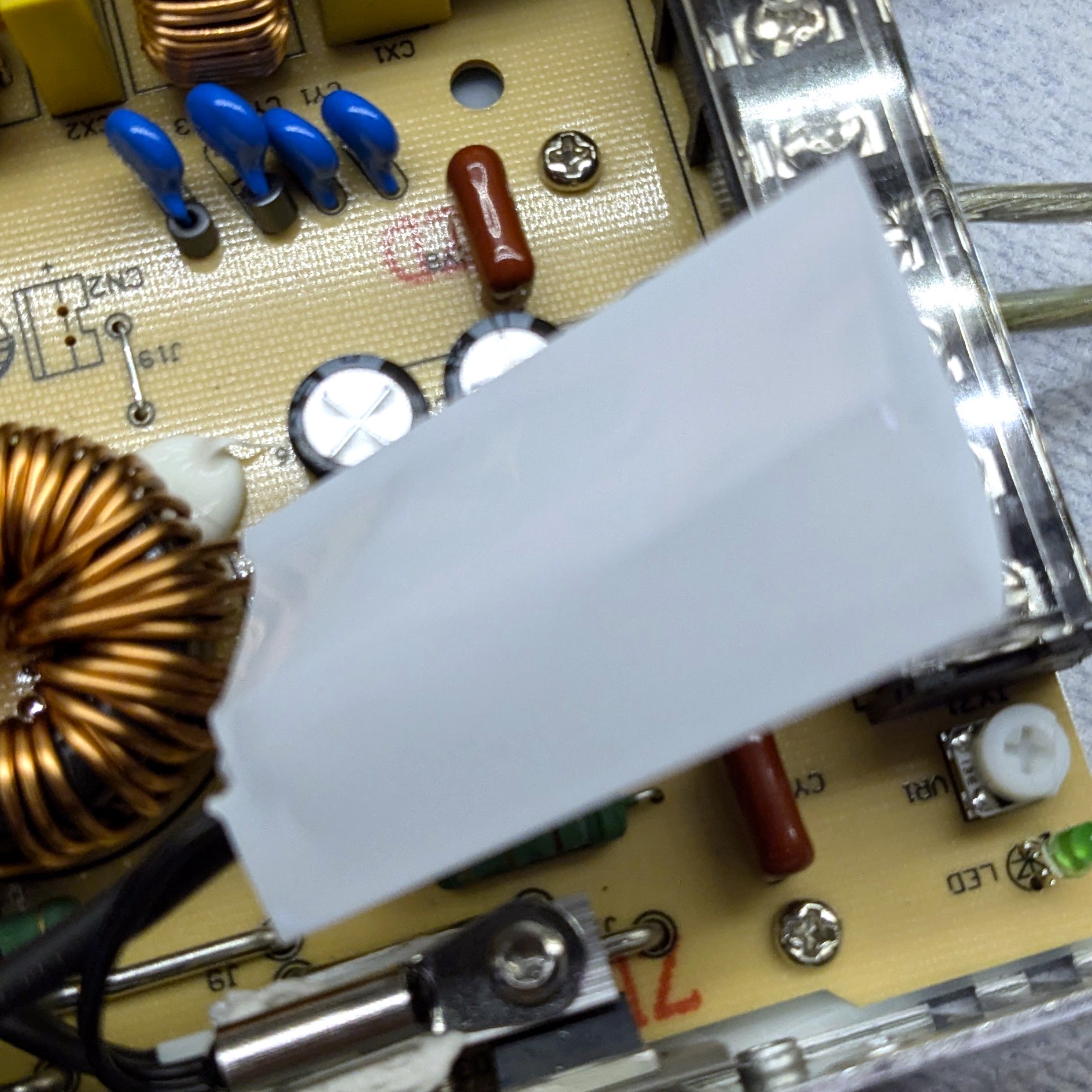
The fan controller was hot-glued to the top of the output capacitors since they stay cool and are conveniently placed.
A test was done operating the power supply at full load for about 10 minutes. I did this to make sure that the fan is still providing sufficient cooling to all components, and it turns out that it is:
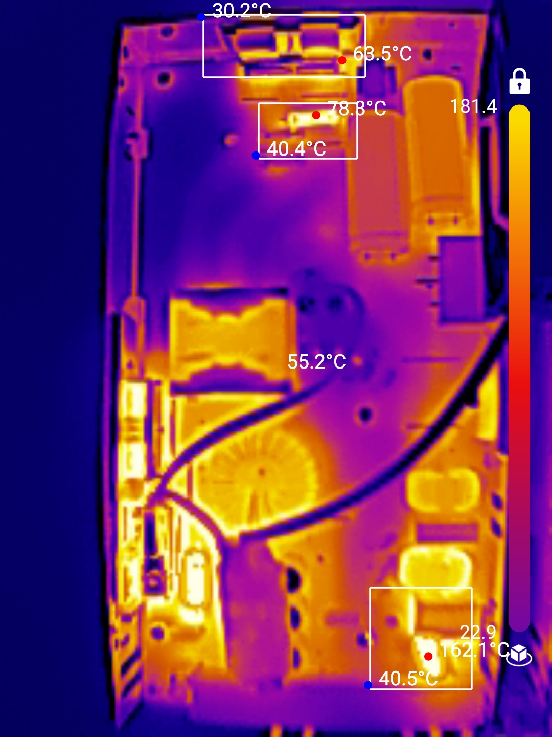
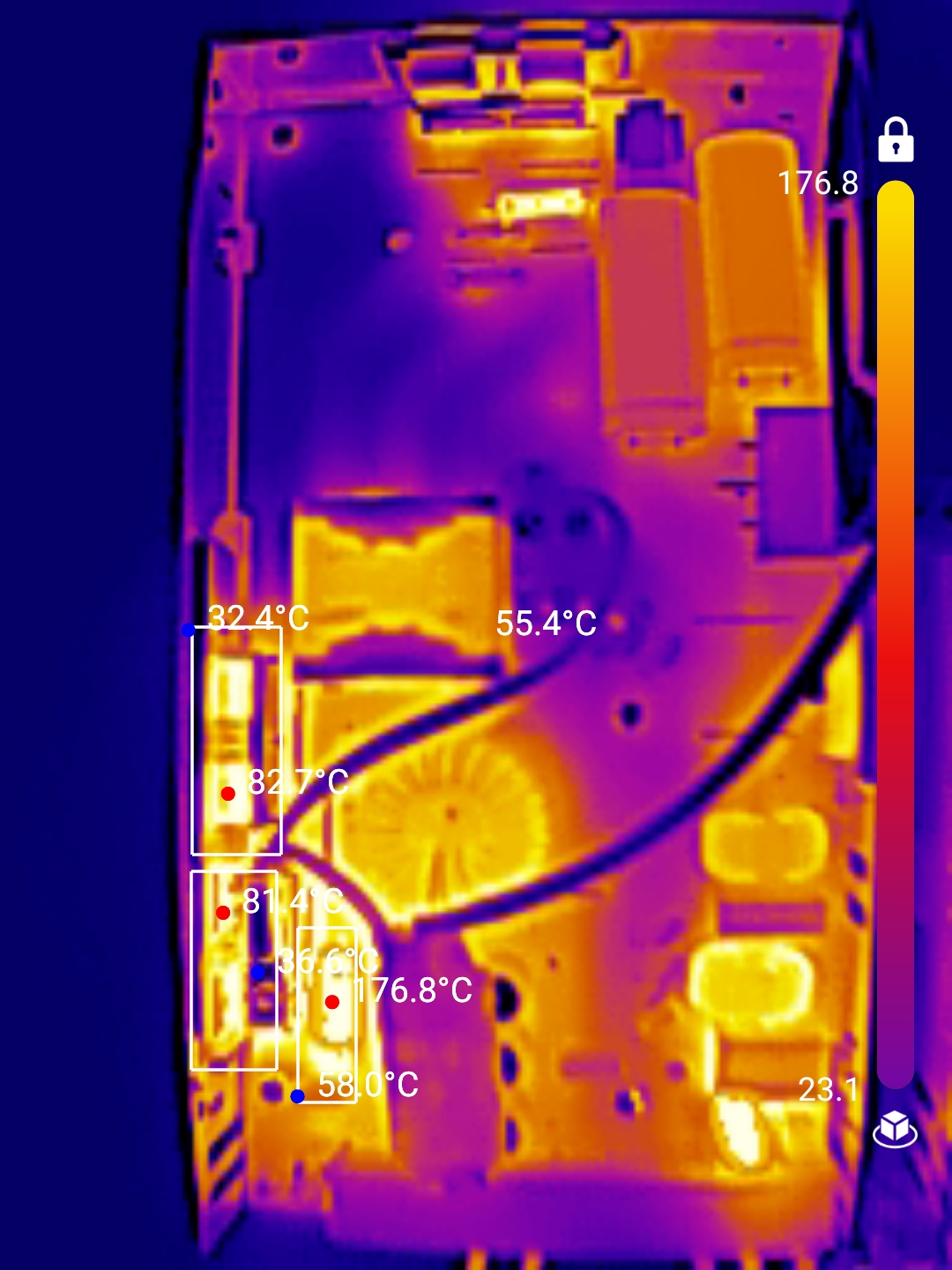
The low-side diodes/switches are getting to a cozy but not unreasonable 82°C, while the hottest components overall are a cement resistor on the output at 176°C, and a inrush limiter at 162°C.